






NEWS
Categories List
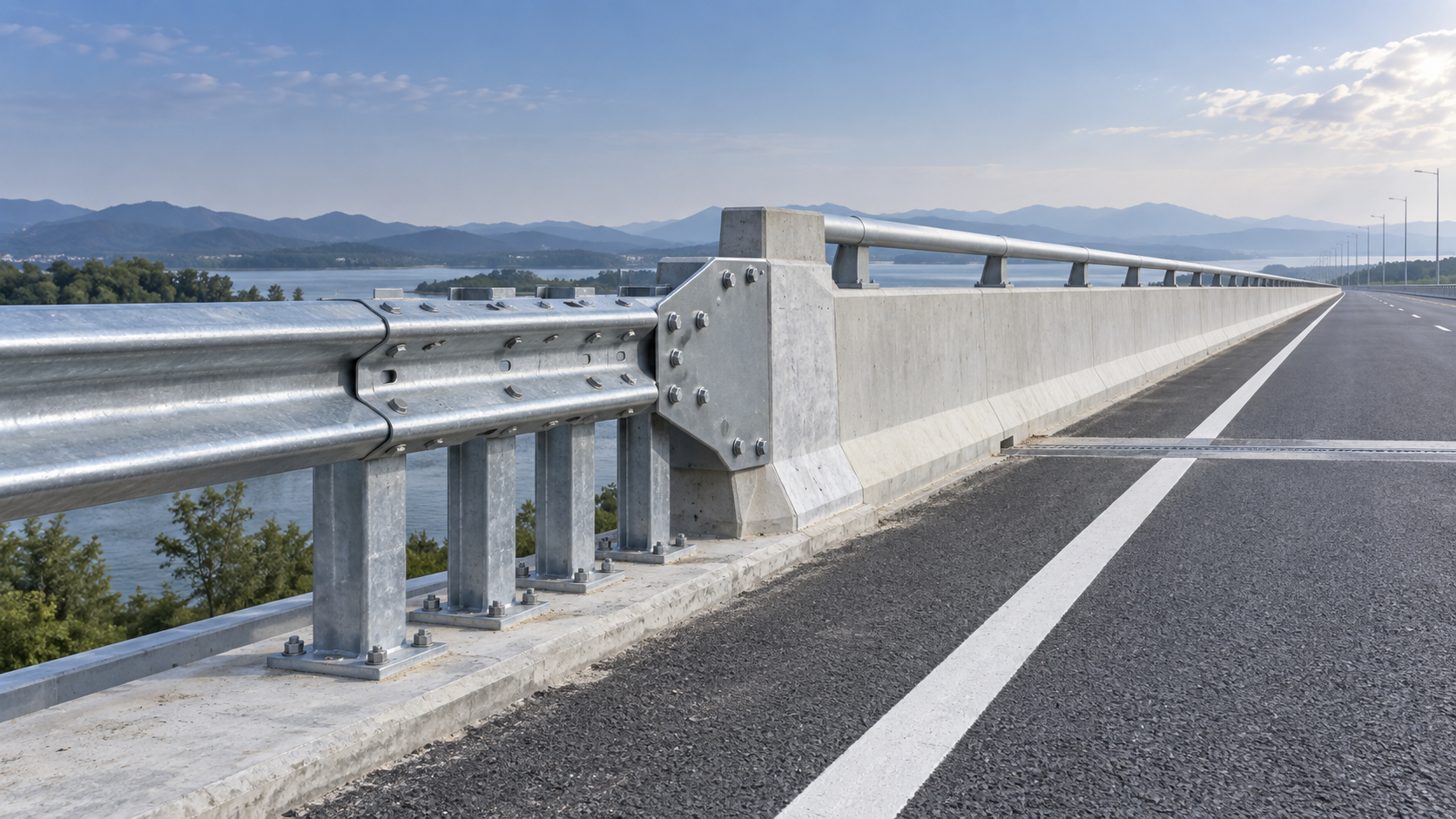
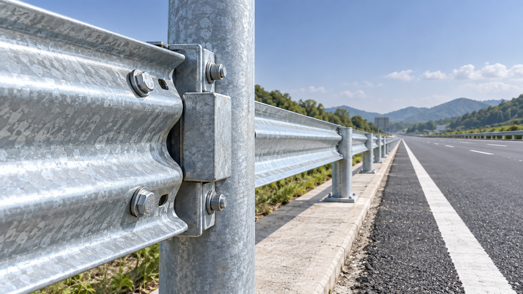
A W Beam Guardrail needs a transition to bridge rail whenever the roadside barrier approaches a bridge parapet, bridge rail, concrete end section, or other substantially stiffer fixed barrier and the guardrail would otherwise terminate abruptly, connect directly without a tested detail, or leave a gap that could expose the bridge structure. The core issue is not simply that two barriers meet; it is that they respond very differently during impact. A W-beam system deflects and distributes load through posts and rail, while bridge rail is usually far more rigid. The change must be managed so that a vehicle is redirected predictably rather than snagging, penetrating, pocketing, or striking an exposed rigid end.
This question often arises during drawing review, quotation comparison, or site coordination: the guardrail alignment looks continuous on paper, but the approach to the bridge has different post spacing, rail height, connection details, and support conditions. Treat that area as a dedicated transition assembly, not as a normal run of W Beam Guardrail with a few extra bolts. The selected detail should be compatible with the bridge barrier, road geometry, containment requirement, and governing project specifications.
The practical trigger: a flexible barrier meets a rigid one
A transition is generally required when an approaching guardrail must guide an impacting vehicle past the end of a bridge rail or into a bridge-mounted barrier. The vehicle should remain redirected along the barrier line, with no abrupt geometry or stiffness change that can create an impact hazard.
Typical conditions that call for a purpose-designed transition include:
- The W-beam run ends at a bridge parapet or concrete rail.
- A steel bridge rail has a different height, profile, or deflection behavior from the roadside guardrail.
- The guardrail must protect an exposed bridge corner, abutment face, wingwall, deck edge, or opening near the roadway.
- The approach barrier is designed to deflect, but the bridge rail has little or no lateral deflection capacity.
- Bridge expansion, drainage features, curbs, sidewalks, utilities, or structural members affect post placement and rail continuity.
- The project drawings show a bridge rail connection but do not identify a complete, compatible transition detail.
A short distance between the bridge and an apparent roadside hazard does not automatically eliminate the need for a transition. The relevant question is whether a vehicle can reach the rigid bridge element or its exposed end from the direction of travel. Barrier layout, approach angle, traffic side, median configuration, and nearby roadside space all influence that judgment.
Why a direct connection can be risky
Joining a W-beam rail directly to a rigid bridge rail may appear economical because both components are steel or both serve as vehicle barriers. Their structural behavior is not interchangeable. Under impact, a conventional guardrail may deflect substantially before developing its redirecting force. A concrete parapet or stiff bridge rail may resist movement almost immediately. If this stiffness change occurs over too short a distance, the rail can deform in an uncontrolled way or transfer force into locations not intended to carry it.
The exposed end of a bridge barrier is especially important. A vehicle approaching at an angle may contact the end, climb the barrier, snag on a projecting member, or be directed toward the structure if the connection geometry is incomplete. A transition is intended to create a controlled progression from the flexible roadside system to the rigid bridge system through coordinated rail sections, posts, blockouts, connectors, reinforcement, and anchorage.
Height continuity matters as much as stiffness. Rail elevation can change because of bridge deck profile, curb treatment, resurfacing, settlement, or differing barrier designs. A small-looking mismatch can become significant when combined with an impact path, heavy vehicle loading, or a raised pavement overlay. Measurements should be taken from the finished roadway surface identified in the project documents, not from an assumed grade.
Do not evaluate the transition as a parts list
A reliable decision starts by reviewing the assembly as a system. It is not enough to compare rail thickness, galvanizing weight, or the number of posts. The evaluator should confirm how the first guardrail posts, bridge-side anchorage, rail splice locations, terminal or transition rail sections, and bridge rail connection work together.
Questions to resolve before selecting or pricing a transition
Start with the bridge barrier itself. Determine whether it is a concrete parapet, steel bridge rail, combination rail, retrofit barrier, or another special structure. Its cross-section, anchorage, height, and permissible connection points determine whether a standard transition detail is usable. A drawing that labels an item only as “bridge rail” is usually not enough for manufacturing or installation planning.
Next, confirm the direction from which the barrier will be struck. A transition may need to work from one direction or both, depending on whether the road is divided, whether traffic can approach from opposite directions, and whether the installation is on a median, shoulder, ramp, or bridge approach. The rail overlap and splice orientation must follow the intended traffic direction and approved design detail.
The approach length also deserves review. The transition section does not replace the length of need for the main guardrail. The W-beam run must begin far enough upstream to shield the bridge-end hazard, accounting for anticipated impact conditions and the barrier’s working width. Moving the transition closer to the hazard merely because it simplifies material quantities can leave the hazard exposed.
Finally, identify constraints that may alter a catalog-style detail: paved shoulders, drainage inlets, retaining walls, buried services, high curbs, slopes, or restricted excavation around the bridge. These conditions can affect post installation and barrier deflection. Any substitution should be reviewed as an engineered change, rather than handled by changing post spacing or omitting members in the field.
Materials and manufacturing details that influence lifecycle value
For procurement, the transition area often has more fabrication-sensitive parts than a standard guardrail run. Components may require nonstandard drilling, bent rail sections, reinforced posts, connection plates, special brackets, or bridge-specific anchor arrangements. Dimensional control is important because a small mismatch between field holes and bridge connection points can delay installation or lead to unauthorized rework.
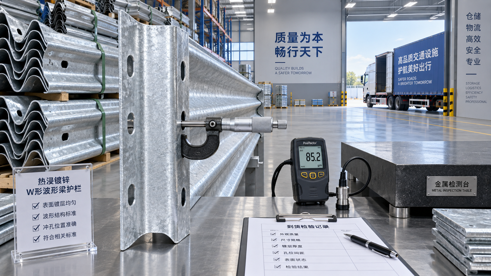
Request production against approved drawings and confirm the scope of processing required for each component. Depending on the detail, this can include drilling, bending, surface preparation, shot peening where specified, non-destructive examination for applicable fabricated items, galvanizing, and painting. Coating treatment should be considered together with the connection design: cut edges, drilled holes, contact surfaces, and site modifications need to remain consistent with the corrosion-protection requirements of the project.
Fasteners should not be treated as generic hardware. Their grade, length, washer arrangement, tightening procedure, and corrosion protection must match the assembly detail. Where an approved design identifies specialized energy-management or connection accessories, procurement should preserve that requirement rather than replacing them with visually similar parts. For example, Spring Steel Buffers should be supplied only where they are specified in the relevant design or bill of materials and their dimensions, material condition, and installation position are confirmed.
Site checks that catch transition problems early
Before installation, compare the actual bridge-end condition with the latest approved drawings. Verify deck edge locations, parapet dimensions, anchor locations, pavement level, curb profile, and available post positions. The bridge construction sequence can change finished elevations or leave embedded items inaccessible, so this check should occur before drilling or fabricating irreversible site modifications.
During assembly, inspect the rail line from the direction of traffic. Look for abrupt offsets, protruding bolt ends where prohibited by the detail, unsupported rail ends, reversed overlaps, incomplete splices, or a sharp change in rail height near the bridge. Confirm that blockouts, posts, brackets, and tensioned or reinforced elements are present in the correct order. A transition can appear complete from one side while still having an incorrect connection sequence on the traffic side.
After installation, retain traceable records for the transition components, including material identification where required, coating information, fabrication inspection, and confirmation that the installed assembly matches the released drawing. This documentation is useful when assessing handover readiness, future resurfacing impacts, repair requirements after a collision, or replacement compatibility years later.
When a standard detail is not enough
A standard transition should not be assumed suitable when the existing bridge rail differs from the barrier type shown in the transition documentation, when bridge geometry forces altered post spacing, or when the approach condition includes a curb, slope, or structural obstruction outside the approved arrangement. The same caution applies to rehabilitated bridges, where existing anchorages and rail sections may not match original drawings.
In those situations, pause the purchase decision until the bridge-side interface, required performance level, and installation constraints are resolved in an approved design. The most cost-effective W Beam Guardrail package is not necessarily the lowest-priced collection of rails and posts; it is the one that can be fabricated, installed, inspected, and maintained as a complete transition compatible with the bridge barrier it is intended to protect.
Leave A Reply
Need More Details?
Contact me for details on creating and managing design projects, project features, and services and prices
consult
Our company was established in 1998. It‘s a Chinese pioneer enterprise integrating production and sales, committed to providing high-quality steel products to customers at home and abroad.

First class quality service and professional after-sales team.
Get in Touch
*We respect your confidentiality and all information are protected.