






NEWS
Categories List

How to Verify W Beam Guardrail Steel Thickness on Delivery
Verifying W Beam Guardrail steel thickness at delivery is not a paperwork exercise. The rail’s ability to deform in a controlled way, transfer loads through the system, and resist premature corrosion depends on the material that actually arrives at the project—not only on the material stated in a quotation or mill certificate.
For quality and safety managers, the challenge is that a guardrail panel has formed corrugations, punched holes, galvanized surfaces, and local areas affected by bending. A quick measurement at one convenient point can be misleading. Reliable acceptance requires a clear distinction between base-steel thickness and coating thickness, a repeatable measurement plan, and records that can be traced to the delivered batch.
Start with the contractual requirement, not the measuring tool
Before opening a bundle, identify what thickness is required by the purchase order, approved drawings, project specification, and applicable standard. “Thickness” may refer to nominal base-metal thickness, minimum base-metal thickness, total thickness after galvanizing, or another defined value. These are not interchangeable.
A W-beam panel is normally formed from flat steel and then hot-dip galvanized. If the requirement concerns structural capacity, the relevant value is generally the steel thickness before zinc coating. A standard micrometer placed on the finished galvanized surface reads steel plus coating. That result may be useful for screening, but it should not automatically be treated as the base-steel value.
The inspector should also confirm whether the specified standard governs the complete roadside barrier system or only the rail material. For example, AASHTO M180 is commonly referenced for corrugated sheet steel beam guardrail, while local project documents may add requirements for dimensions, galvanizing, bolt holes, testing, marking, or acceptance sampling. Where a Brazilian specification is involved, the project should clarify the exact ABNT requirement and the edition being applied rather than relying on a broad standard name alone.
Separate the documents into three checks
A good receiving inspection combines documentation with physical verification. Neither one is sufficient in isolation. Certificates can confirm the intended input material, while measurements establish whether the delivered components are consistent with that documentation.
- Purchase and drawing review: confirm panel profile, nominal thickness, steel grade if specified, coating system, length, hole pattern, and permitted tolerances.
- Traceability review: compare bundle tags, heat numbers, production lot numbers, packing lists, and mill test certificates. A certificate with no clear connection to the delivered bundles has limited value.
- Physical inspection: verify dimensions, thickness, coating condition, hole quality, damage, and visible consistency across the shipment.
Do not accept a certificate simply because it lists an acceptable thickness. Check that the document identifies the relevant coil, plate, or production lot and that the quantities can reasonably be reconciled with the delivery. Mixed bundles are a common source of confusion, especially where rails, terminal components, posts, and hardware are delivered together.
Use the right method for base steel and zinc coating
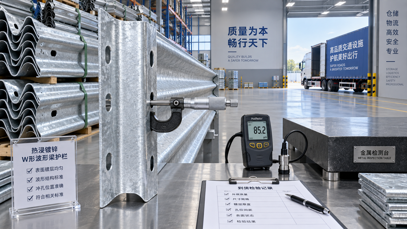
For incoming W Beam Guardrail inspection, a calibrated outside micrometer is often the most practical tool for a rapid dimensional check. It should have suitable measuring faces, enough throat depth for the selected location, and a calibration status that meets the project’s quality procedure. Digital calipers are useful for overall dimensions but are generally less suitable than a micrometer where close thickness verification is required.
Because galvanizing is included in the reading, use micrometer values carefully. If the project requires verification of base steel after galvanizing, the acceptance procedure should state how coating is accounted for. Depending on the contract and available equipment, this may involve testing a designated coupon, measuring the coating separately with a suitable magnetic thickness gauge, or using an agreed laboratory method. Removing zinc from an arbitrary finished panel merely to obtain a steel reading can create a corrosion risk and should not be done without an approved method.
A magnetic coating thickness gauge is designed to estimate the zinc layer on ferrous steel. It is valuable for checking galvanizing uniformity and detecting suspiciously low or inconsistent coating areas. It does not directly tell the inspector whether the underlying steel meets the specified thickness. Record steel and coating readings as separate results.
Where to measure on a W-beam panel
Measurement location matters as much as instrument selection. Avoid using only the crest of the corrugation, a sharp bend radius, an edge, or the immediate area around a punched hole. Those locations can produce unstable readings or reflect local deformation from forming and punching.
Unless the governing specification provides its own locations, take readings on reasonably flat, accessible areas of the web away from holes, cut ends, deep bends, labels, welds, and obvious handling damage. Measure more than one point on each selected rail and sample rails from different bundles, not just the top panels of one stack. If the supply includes different rail lengths or production lots, treat them as separate populations for inspection purposes.
The sampling quantity should follow the project inspection plan or applicable standard. Where no sampling rule has been established, the receiving team should agree on one before delivery and apply it consistently. Increasing the number of checks is sensible when there are mixed heat numbers, inconsistent surface appearance, missing traceability, or an earlier nonconforming result.
A practical receiving sequence
Inspection is easier when it happens before the rails are dispersed across the site. Keep bundles accessible until the initial release decision is made. A practical sequence is to photograph the bundle labels, assign an inspection reference, select samples across the shipment, and record every reading against the relevant bundle or lot.
- Check quantity, rail profile, nominal length, hole arrangement, and visible damage against the packing list and drawings.
- Confirm that bundle identification matches certificates and production records.
- Clean only loose dirt or moisture from the measuring area; do not grind or abrade the galvanized coating for a routine check.
- Zero the micrometer, take repeated readings at the defined locations, and record the actual values rather than writing only “pass.”
- Check coating condition separately for bare areas, rough zinc build-up, runs, white storage stain, or impact damage from transport.
- Place suspect bundles on hold until the supplier, contractor, and project quality representative agree on disposition.
The inspection record should state the instrument identification, calibration due date, inspector, delivery date, project reference, sample locations, readings, document references, and disposition. This level of detail is especially helpful if panels are later found to vary during installation or if a road authority requests evidence of material control.
Thickness issues that visual inspection can miss
A rail may look substantial while still being unsuitable for the specified system. Galvanizing can make a thinner sheet appear robust, and a clean surface does not confirm the material underneath. Conversely, a slightly different micrometer result does not necessarily establish nonconformance unless the acceptance basis, coating contribution, tolerance, and measurement location are understood.
Other warning signs deserve attention even when thickness readings appear acceptable: elongated or poorly aligned holes, flattened corrugations, cracks at bends, inconsistent panel geometry, deep handling dents, and areas where zinc has been damaged after galvanizing. Guardrail performance depends on the interaction of rail, posts, blockouts, fasteners, terminals, and installation geometry. A compliant sheet thickness alone cannot compensate for incorrect components or field assembly.
For projects using systems aligned with ABNT 6971 or AASHTO M180 requirements, the review should extend beyond the W-beam panel. The intended post type, splice arrangement, hardware, galvanizing requirement, and installed configuration all need to match the approved design. This is particularly relevant on hazardous road sections, where the barrier is expected to absorb impact energy and guide a vehicle back toward its normal travel path.
When a supplier’s manufacturing controls matter
Delivery inspection is the last practical checkpoint, not the only quality control point. Better outcomes begin with manufacturing controls: confirming incoming steel, controlling drilling and bending, removing contaminants before galvanizing, checking dimensions after forming, and maintaining traceability through packing. Where drawings call for additional fabrication steps, such as shot peening, non-destructive testing, painting, or specialized rust removal, those activities should be documented against the applicable requirement rather than assumed from a general process description.
For example, the Brazil ABNT 6971 Guardrail is specified for highway and hazardous-section applications with hot-dip galvanized protection and references ABNT 6971 and AASHTO M180. Its stated service-life expectation of over 20 years should be read in the context of the project environment, coating requirement, installation quality, and maintenance exposure. Thickness verification remains one part of confirming that the delivered system corresponds to the approved design.
If readings are borderline, documentation is incomplete, or the project specification is unclear about coated versus uncoated thickness, do not resolve the issue by informal judgment at the unloading area. Hold the affected material, identify the relevant lot, and request a written technical clarification. A defined acceptance method protects the project team, the supplier, and ultimately the road users who depend on the barrier performing as designed.
Leave A Reply
Need More Details?
Contact me for details on creating and managing design projects, project features, and services and prices
consult
Our company was established in 1998. It‘s a Chinese pioneer enterprise integrating production and sales, committed to providing high-quality steel products to customers at home and abroad.

First class quality service and professional after-sales team.
Get in Touch
*We respect your confidentiality and all information are protected.