






NEWS
Categories List
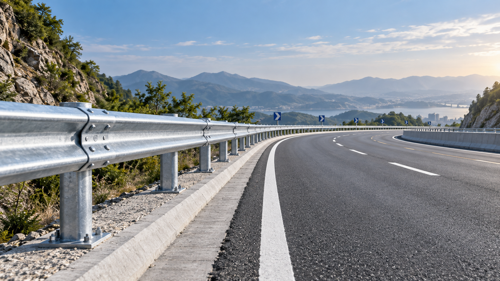
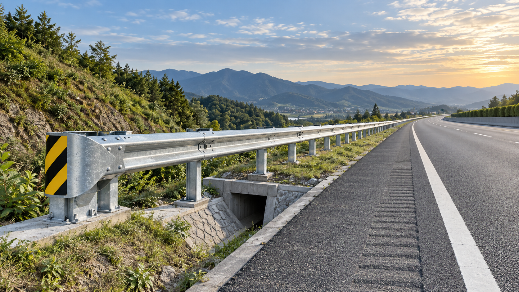
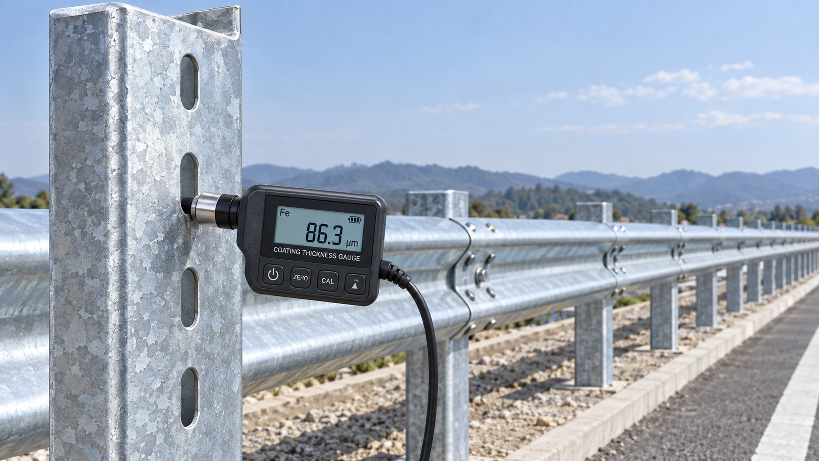
A W-beam guardrail can follow a tight horizontal curve, but it should not be treated as a straight run that has simply been bent in the field. The rail geometry, post layout, splice orientation, terminal arrangement, and available deflection space all change as the radius decreases. A curve that appears manageable on a plan may create installation strain, distorted slots, inconsistent rail height, or an untested system configuration once construction begins.
The practical answer is therefore conditional: a W Beam Guardrail can be used on a tight curve when the selected barrier system has a documented curved installation detail, the rail is fabricated or formed for the required radius, and the complete assembly remains consistent with the governing roadside safety standard and project drawings. Where these conditions are not met, forcing standard straight rail sections into alignment creates avoidable containment and maintenance risk.
Curvature is not only a fabrication question
W-beam rail has enough longitudinal flexibility to accommodate gradual horizontal alignment changes through normal splices. Tight curves are different. As the required radius becomes smaller, the corrugated profile, bolt slots, splice overlaps, and rail-to-post connection points are subjected to greater geometric demand. The issue is not whether steel can physically bend. It is whether the finished barrier retains the intended height, continuity, stiffness, and impact behavior.
A guardrail is a system rather than an isolated steel component. The rail redirects an impacting vehicle by developing tension along its length while posts, blockouts, soil support, and splice connections control how that force is transferred. Curving the rail changes the initial geometry of that system. If a rail segment is improperly bent, the beam may twist, flatten locally, or create uneven stress around bolt holes. If the posts are installed on a chord line rather than the actual curve, the rail can be pulled into place under permanent strain. These conditions may not be visually obvious after installation, but they can affect durability and response under impact.
The decision should therefore begin with the actual curve radius, transition locations, design speed, roadside hazard, barrier length, required containment level, and the standard applicable in the project jurisdiction. A statement that a supplier “can bend W-beam” is not sufficient evidence that the resulting installation is suitable for the specified roadside barrier system.
What makes a curve “tight” in guardrail design
There is no universal radius below which W-beam guardrail automatically becomes unsuitable. Acceptable curvature depends on the tested or approved system, rail length, steel grade and thickness, post type, offset block design, and installation details prescribed by the road authority. A radius acceptable for one proprietary or agency-approved configuration may be outside the permitted range for another.
From a procurement and project-control perspective, a curve should be considered critical when one or more of the following conditions applies:
- The alignment requires visible forcing of rail sections during installation.
- Standard splice holes no longer align naturally without reaming, slot modification, or excessive bolt tension.
- Post spacing must change from the approved arrangement merely to make the rail follow the line.
- The rail approaches a bridge parapet, rigid barrier, terminal, gate, driveway opening, or drainage structure within the curved section.
- The available space behind the barrier is reduced by the curve, slope, obstruction, or adjacent structure.
- The curved run creates a short segment between two different barrier types or between a barrier and an end treatment.
These are not minor installation inconveniences. They indicate that the barrier should be reviewed as a special layout condition rather than ordered as standard straight stock.
Shop-curved rail is generally more controllable than field forcing
For demanding radii, shop-curved W-beam sections provide a more predictable result than bending standard rail during installation. Controlled forming can be matched to a specified radius and direction while maintaining dimensional consistency across a batch. It also allows inspection before delivery for distortion, damage to galvanizing, unintended twisting, and bolt-hole alignment.
Field adjustment still has a place for gentle alignment corrections, but it should not become the method for achieving a planned tight-radius curve. Uncontrolled bending can introduce several problems:
- local deformation of the W profile, reducing the intended section shape;
- damage to zinc coating or paint systems, increasing corrosion exposure;
- misalignment at splices, affecting rail continuity and bolt engagement;
- variation in rail height as the beam twists around the curve;
- inconsistent setback from the roadway edge or hazard being shielded.
The manufacturing specification should state the required centerline radius, concave or convex bending direction, rail section length, hole pattern, galvanizing or coating requirement, and permitted dimensional tolerances. The supplier should also confirm whether bending occurs before or after galvanizing and how coating integrity is protected. This is particularly relevant in coastal, industrial, or high-moisture locations, where damage at a bent edge or bolt hole can become a long-term maintenance issue.
Post spacing cannot be changed casually
A common mistake is to reduce or vary post spacing on a curve simply because it makes the rail easier to fit. Closer spacing may appear conservative, but it changes the stiffness of the system and can alter its deflection behavior. Wider spacing may reduce material use or simplify placement, but it can weaken support where the rail needs it most. Neither adjustment should be made without confirming that it is allowed by the approved design.
Post locations should be set from the designed guardrail alignment, not improvised after the rail arrives. On a curve, this normally requires careful survey control and attention to the relationship between the rail face, roadway edge, shoulder width, and protected object. The posts must also be suitable for the ground condition. Rock, buried services, retaining structures, drainage runs, and compacted fill can affect embedment and post resistance. A perfectly curved rail does not compensate for inadequate post support.
Rail height deserves equal attention. Changes in grade often occur near horizontal curves, particularly at ramps, bridge approaches, intersections, and terrain transitions. Measuring height only at selected posts can miss a gradual rise or fall between supports. The final height should be checked along the rail line using the project’s specified reference plane, because a low point can increase underride risk while an excessively high point may affect vehicle interaction.
Splices and rail orientation matter more on curves
W-beam splices are not interchangeable visual joints. Their overlap direction, bolt arrangement, and position relative to traffic are part of the system design. On a curved alignment, incorrect orientation can create an exposed edge or snag point for an errant vehicle. Splices should follow the approved direction of traffic and the manufacturer’s installation detail, including bolt type, torque requirements where specified, and the use of all required fasteners.
Curving also increases the importance of preserving consistent contact between the rail, blockout, and post. The purpose of the blockout is not merely to create a gap. It helps maintain rail position and reduces the chance that a vehicle wheel or body will strike the post directly. If the rail is pulled sideways to make a curve fit, blockouts can rotate or sit unevenly, producing an installation that looks complete but no longer reflects the intended geometry.
Where the layout includes a transition to a bridge rail, concrete barrier, or other rigid feature, the curved section should be evaluated with particular caution. Transitions manage the shift from a flexible system to a much stiffer one. Combining that stiffness change with a short-radius horizontal curve can concentrate demand in a limited length of rail. The layout may require a longer transition, a revised barrier line, or a different approved system rather than a sharper bend.
Containment performance depends on more than the rail’s ability to turn
Roadside barriers are evaluated under defined crash-test and acceptance frameworks, such as MASH in the United States or EN 1317 in many other markets. These frameworks assess complete barrier systems under specific configurations. A supplier’s material certificate, galvanizing record, or dimensional inspection does not by itself establish that a custom curved installation provides the same performance as a tested straight configuration.
This does not mean every curved installation requires a new full-scale crash test. It means that the designer and approving authority must determine whether the proposed radius, post spacing, rail geometry, terminal arrangement, and transition detail fall within an accepted design envelope. The responsible design authority should resolve deviations before fabrication, not after rail has been delivered to site.
For projects that refer to an existing standard drawing, the key question is whether the drawing expressly permits the required radius and installation arrangement. If it does, fabrication and construction should follow that detail exactly. If it does not, the project needs an engineered amendment or a barrier system with documented suitability for the condition. Treating the absence of a restriction as approval is a poor risk decision.
Deflection space often becomes the real constraint
A curved guardrail is frequently installed because the roadway is close to a fixed hazard: a culvert headwall, steep slope, bridge support, retaining wall, utility structure, or roadside sign foundation. Yet the tighter the curve, the more likely the barrier is being placed in a constrained corridor. That makes working width and dynamic deflection central to the selection decision.
During an impact, a flexible W-beam system moves laterally. If there is insufficient clearance behind the rail, the vehicle, rail, or posts may contact the hazard that the barrier was intended to shield. Moving the barrier closer to the hazard does not solve this problem; it can reduce available deflection distance further. The correct response may involve changing the barrier offset, extending the length of need, selecting a stiffer approved system, modifying the hazard, or adopting a different roadside treatment.
The curve also affects the length of need. On straight roadway, the barrier can often be aligned parallel to the hazard. On a bend, a vehicle departure path and the barrier’s shielding line may not be intuitive from a plan view alone. The upstream and downstream ends must be evaluated in relation to likely vehicle trajectories, not only the point where the physical obstacle begins.
Terminals should not be treated as bendable extensions
End terminals and anchor arrangements are highly configuration-sensitive. They are designed to develop rail tension, absorb energy, redirect vehicles, or allow controlled end-on behavior depending on the system. Placing a terminal inside a tight curve, changing its flare, or altering its alignment to match a constrained site can invalidate the intended installation detail.
Where a curved guardrail run ends near a junction, access road, median opening, or bridge approach, the layout should be resolved around the terminal first. The rail line can then be designed to reach that terminal using approved geometry. Starting with the desired curved rail path and forcing the terminal into the remaining space reverses the safety logic.
Special components may be considered only where they belong to an approved assembly. For example, Spring Steel Buffers may have a role in particular engineered steel assemblies or accessory arrangements, but they should never be assumed to improve a guardrail curve simply because they add flexibility or energy absorption. Any accessory that changes load transfer, rail movement, or terminal behavior requires confirmation against the system design.
What to require before releasing a curved guardrail order
The most effective control is to resolve the curve as a documented engineering condition before purchase. The order package should include plan and profile information, exact radius, rail line coordinates where available, post schedule, barrier offset, splice direction, terminal and transition details, coating requirements, and applicable acceptance standard. A fabrication drawing should show the direction of curvature and identify each non-standard rail piece clearly enough to prevent reversal during installation.
It is also prudent to require traceability for the steel and protective coating, dimensional inspection of curved sections, and a practical installation sequence. The sequence matters because rails installed in the wrong order can lock in alignment errors that become difficult to correct near a terminal or transition. Delivery packaging should protect curved pieces from stacking damage and make it easy for site crews to identify the intended installation location.
For the decision-maker, the central distinction is straightforward: paying for properly engineered curved fabrication and controlled layout is not an aesthetic upgrade. It is a means of avoiding a barrier that fits the road visually but departs from the geometry and system behavior on which its safety function depends. A W-beam guardrail can follow a tight horizontal curve, but only when the curve is treated as part of the barrier design—not as a field adjustment after the design is complete.
Leave A Reply
Need More Details?
Contact me for details on creating and managing design projects, project features, and services and prices
consult
Our company was established in 1998. It‘s a Chinese pioneer enterprise integrating production and sales, committed to providing high-quality steel products to customers at home and abroad.

First class quality service and professional after-sales team.
Get in Touch
*We respect your confidentiality and all information are protected.