






NEWS
Categories List
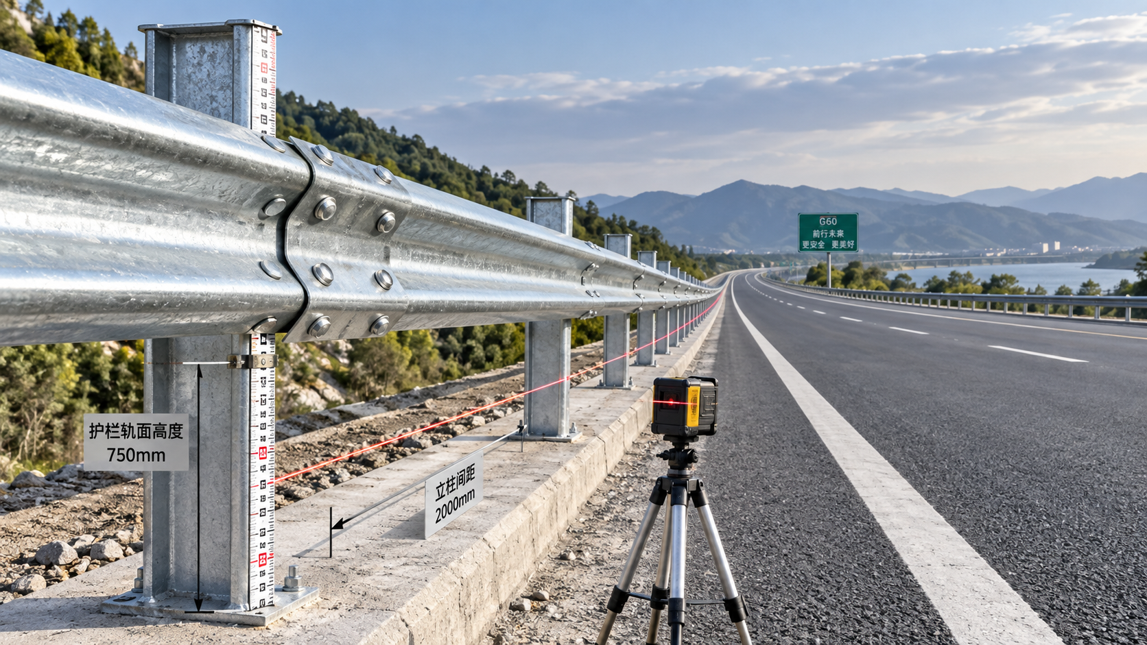
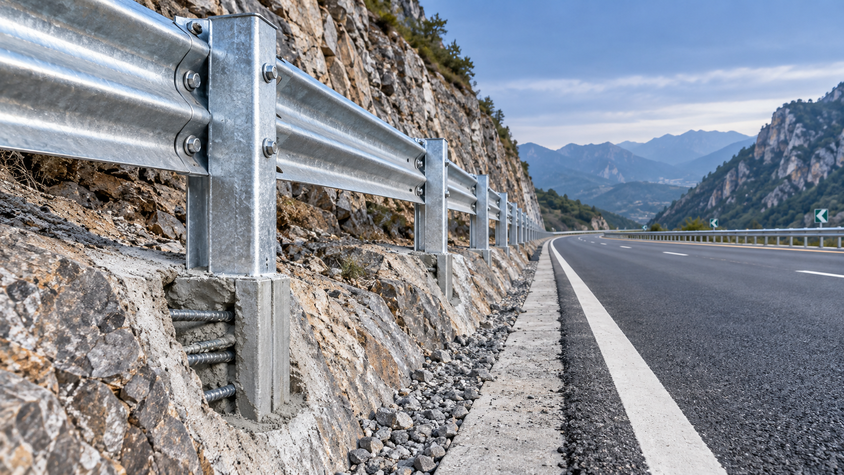
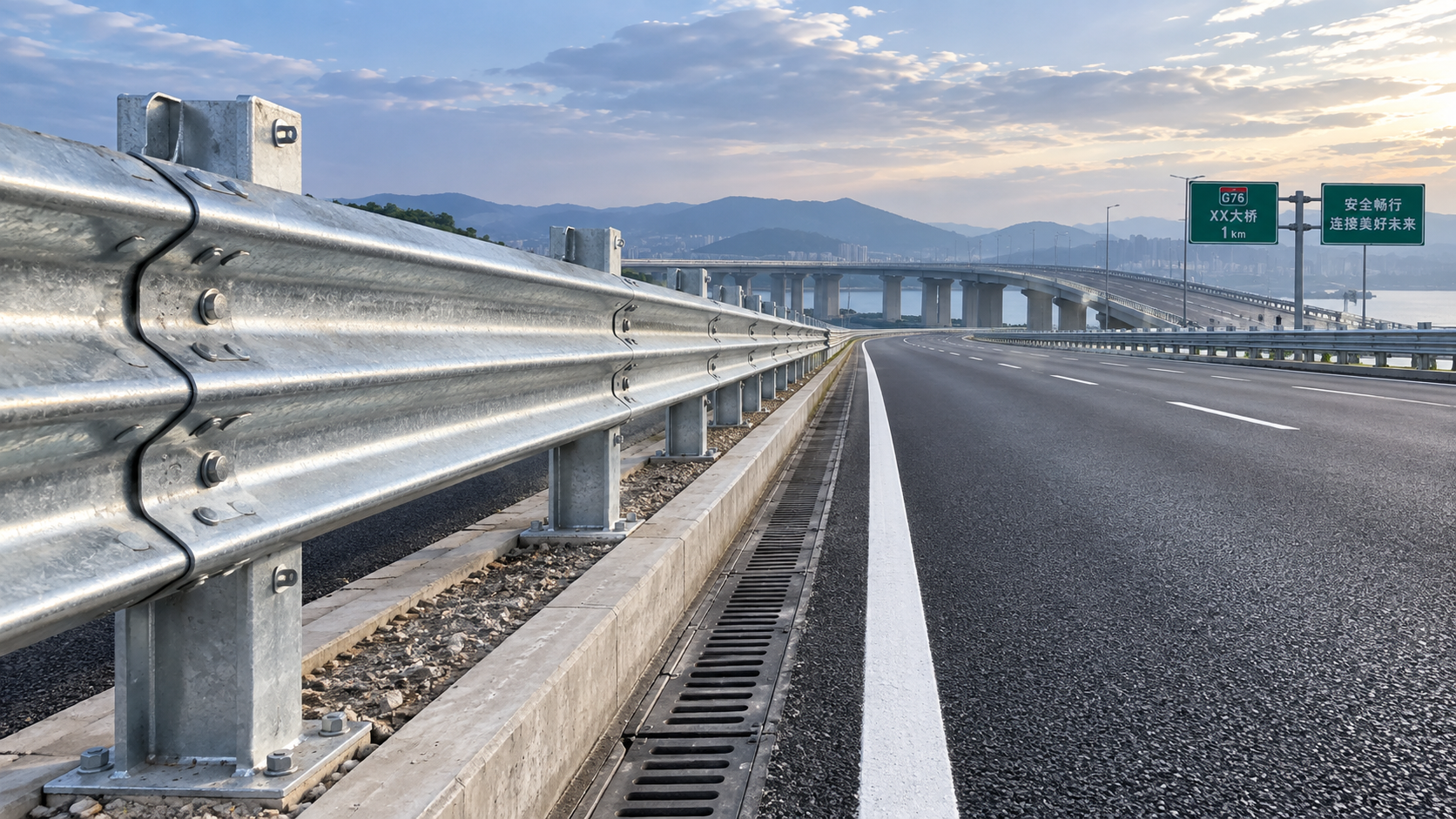
Once the rail has been installed, an alignment issue in a Z Post Guardrail can be easy to overlook from a distance. A barrier may appear continuous while individual posts are leaning, rail height is drifting, or splice connections are pulling the line out of position. These deviations can affect how the system responds under impact, create snag points, and make future maintenance more difficult.
The most reliable approach is to inspect the completed barrier against the approved layout drawings and installation requirements, starting with the overall line of the system and then moving to post position, rail elevation, embedment, and connections. Do not judge alignment by visual appearance alone. A rail can look straight from one viewing angle while being out of level, offset at a splice, or incorrectly positioned relative to the roadway edge.
Begin with the reference line, not the rail face
Before measuring individual components, establish the intended guardrail line from the project setting-out information. This may be the roadway alignment, the barrier offset line, a surveyed control line, or the dimensions shown on the approved drawings. The inspection team should confirm which reference governs before recording deviations.
Walk the full installed length from both travel directions. Look for changes in curvature, sudden inward or outward movement, and areas where the rail seems to “wander” between posts. A gradual curve may be correct where the road geometry requires it; a local bend between otherwise consistent sections usually needs closer examination. Pay particular attention to transition areas, bridge approaches, median openings, ramp noses, and locations where the barrier changes height or joins another protective system.
Use a string line, laser, total station, or other suitable surveying method to compare the actual installation with the design line. The selected method should be accurate enough for the project’s specified acceptance criteria. Record the chainage or station of any deviation rather than relying on general notes such as “rail out of line.” Clear location records make corrective work faster and prevent a localized problem from being missed during reinspection.
Check post spacing and position before judging the rail
Misaligned rails are often a symptom of incorrectly placed posts. Measure centre-to-centre spacing between adjacent Z posts and compare it with the approved layout. Spacing must remain consistent with the designed barrier configuration, especially near terminals, transitions, curved sections, expansion zones, and special supports. A post that is only slightly misplaced can force installers to pull the rail, elongate a bolt hole improperly, or create a visibly uneven rail line.
Each post should also be checked for lateral offset from the reference line. A single post pushed too far toward the traffic side or away from it may change the effective position of the rail face. This can reduce the intended clearance to a hazard, conflict with drainage features, or create an irregular barrier path that affects redirection behavior.
- Measure post centres rather than estimating spacing from rail corrugations or bolt locations.
- Confirm that the first and last posts in a run are located as detailed, since errors at these points can affect the entire section.
- Inspect curved runs with shorter measurement intervals; a long chord can conceal a local kink.
- Check that posts are not rotated in a way that twists the rail or prevents correct blockout and bracket seating.
Where a post is out of location, determine whether the rail has been forced to fit it. Loosened bolts, stressed splice plates, distorted slots, or uneven gaps at connections can indicate that the assembly is compensating for incorrect post placement. Correcting only the rail position without addressing the post may leave residual stress or an inaccurate final geometry.
Verify plumb, embedment, and soil-related movement
A Z post must be installed at the required depth and orientation so that the rail support behaves as designed. Check verticality in both the longitudinal and transverse directions using an appropriate level, plumb instrument, or survey equipment. Posts on sloped terrain may follow a drawing-specific orientation, so the inspector should not assume that every member must be visually vertical relative to the road surface.
Look for signs that driving or excavation conditions have affected the post: ground heave around the flange, cracked pavement edges, disturbed backfill, loose soil, tilted posts, or a line of posts leaning in the same direction. These conditions can occur where subsurface materials change, where buried obstructions are encountered, or where a post has been driven and then pulled back without a defined corrective procedure.
Embedment depth should be verified using the approved installation method and project requirements. If direct depth measurement is not possible after installation, use documented driving records, known post length, top elevation, and surveyed ground level as applicable. Do not accept a visibly uniform top elevation as proof of equal embedment; uneven ground can make shallow and deep posts appear similar from the roadway.
Distinguish intentional grade changes from installation errors
On a rising or falling roadway, the rail may follow the grade rather than remain level. The concern is not whether the rail appears horizontal, but whether it follows the specified vertical profile without abrupt changes. Sudden dips can reduce rail height locally. Sudden rises can create a stiff point, interfere with vehicle contact geometry, or make a splice difficult to seat correctly.
Measure rail elevation at regular intervals and at every visible change in grade. Compare the measurements with drawing elevations or the permitted installation criteria. Inspect both rail height above finished ground and continuity between adjacent panels. Ground level should be checked near each post where erosion, paving variation, or grading work could change the effective rail height after installation.
Inspect rail height, overlap direction, and splice condition
Rail height is one of the most important completed-installation checks. Measure from the finished ground surface or the specified reference surface to the required point on the rail profile. Use the same measurement basis throughout the inspection. Measuring from loose soil in one location and compacted shoulder material in another can create misleading results.
At each splice, verify that adjacent rail sections overlap in the direction required for traffic approaching from each applicable direction. Incorrect overlap direction can leave an exposed edge or an undesirable contact condition. Examine the joint for full seating, correct bolt placement, appropriate washers where specified, and bolts tightened in accordance with the installation requirements. A splice that is visibly stepped, open, or pulled sideways may indicate a post-spacing error, rail damage, incompatible components, or an attempt to close an incorrect gap.
Connection hardware should be secure without crushing, tearing, or deforming the rail. Bolt holes must not be field-modified unless the approved design explicitly permits it. New holes, torch-cut slots, and forced alignment through excessive bolt tension should be treated as nonconforming conditions because they can alter load transfer and corrosion protection.
Examine high-risk sections more closely
Alignment checks deserve extra attention where the barrier must perform around fixed hazards or where geometry changes rapidly. Bridge sections, pier protection zones, lighting poles, median-strip openings, ramp divergences, and high-risk expressway sections may use stiffer or specially configured connections. In these locations, the barrier line, clearances, and connection geometry should match the detailed design rather than a general field assumption.
Where a high-stiffness connector is specified, inspect it as part of the alignment system, not as a separate piece of hardware. A Fish Plate Connector made from high-quality hot-rolled steel plate can be used where higher bending stiffness and impact resistance are required. Its function depends on correct seating, bolt alignment, and compatibility with the rail and post arrangement. Even a robust connector cannot compensate for a rail run that is pulled out of line or posts that are improperly positioned.
Check coated surfaces after any adjustment. Zinc-aluminum-magnesium and powder-coated components can be damaged by uncontrolled pulling, striking, or abrasive field modification. Scratches, exposed steel, damaged coating around bolts, and deformation at drilled areas should be assessed according to the project’s repair requirements. Coating condition matters especially in coastal or high-salt-fog exposure, where long-term corrosion resistance depends on preserving the protective system.
A practical sequence for documenting acceptance
- Review approved drawings, barrier layout, component schedule, and any approved installation changes.
- Survey the overall barrier line and identify sections with lateral drift, sharp kinks, or unexpected curvature.
- Measure post spacing, post offset, rail height, and rail profile at the intervals required by the project, adding measurements at transitions and visible irregularities.
- Check post plumb and confirm embedment evidence through installation records or approved verification methods.
- Inspect splices, brackets, blockouts, bolts, and specialized connectors for proper fit, orientation, and signs of forced assembly.
- Record nonconformities by precise location, describe the condition, and note whether the issue affects geometry, connection integrity, coating, or clearance.
- Reinspect corrected areas after adjustment rather than accepting a repair based only on installer confirmation.
When deviations are found, avoid deciding on site that a bent rail can simply be pulled straight or that a leaning post can be accepted because the rail remains connected. The appropriate correction depends on the design system, the extent of deformation, ground conditions, and the affected location. Components showing permanent bending, damaged holes, compromised coating, or forced connection geometry may require replacement rather than adjustment.
A completed Z Post Guardrail should read as a controlled system: posts located on the intended line, rail elevation following the designed profile, connections seated without stress, and protective clearances maintained around hazards. Inspecting these elements together provides a more dependable acceptance decision than relying on any single measurement or visual impression.
Leave A Reply
Need More Details?
Contact me for details on creating and managing design projects, project features, and services and prices
consult
Our company was established in 1998. It‘s a Chinese pioneer enterprise integrating production and sales, committed to providing high-quality steel products to customers at home and abroad.

First class quality service and professional after-sales team.
Get in Touch
*We respect your confidentiality and all information are protected.