






NEWS
Categories List
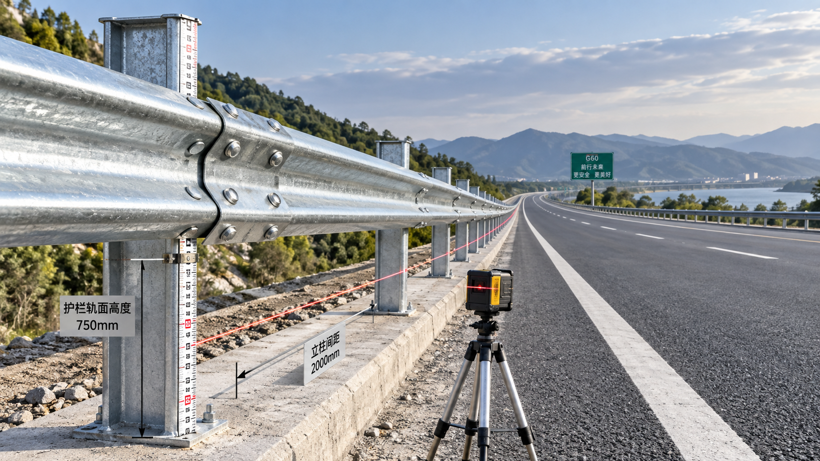
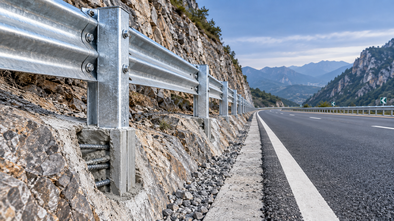
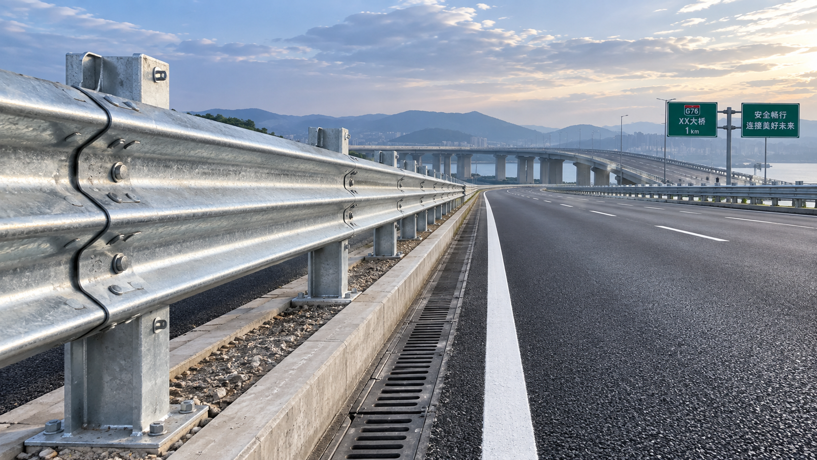
Yes, a Z post guardrail can be installed effectively in rocky ground, but only when the installation method is matched to the actual rock profile rather than treated as a standard driven-post operation. Rock is not a single condition: shallow fractured rock, competent bedrock, mixed soil-and-rock shoulders, and boulder-filled fill create very different foundation behaviors. A post that appears firmly seated after driving may still have inadequate embedment, uncontrolled tilt, damaged galvanizing, or poor resistance under lateral impact.
The central question is therefore not whether rock makes a Z Post Guardrail impossible. It is whether the selected post length, hole geometry, anchorage method, and inspection criteria can deliver the intended barrier behavior without changing the tested or approved system configuration. Where driving cannot achieve the specified installation condition, drilling and grouted installation, localized excavation and concrete backfill, or a redesign of the support arrangement may be necessary.
Why rocky ground changes guardrail performance
A conventional driven post relies on confinement and lateral support from surrounding soil over its embedded length. In competent rock, the post may stop abruptly before reaching its intended depth. In layered or weathered rock, it may follow a fissure, deflect sideways, or create a misleading impression of resistance while bearing only against isolated rock fragments. Boulder-rich material creates a similar problem: a refusal point can be caused by one obstruction rather than by a stable foundation.
These conditions affect more than installation productivity. They can alter post spacing, rail height, longitudinal alignment, and the way impact forces are transferred through the barrier. A barrier line with several shallow or misaligned posts can have inconsistent stiffness. That inconsistency matters particularly near bridge approaches, ramps, median openings, lighting structures, and other locations where containment and guidance performance are critical.
Rock also increases the risk of coating damage. Repeated hammering against hard inclusions can scrape galvanized surfaces or deform the flange edges of the post. If coating damage is not assessed and repaired using an approved method, corrosion can begin at the damage point even where the rest of the guardrail system has durable protection.
Site investigation must distinguish refusal from suitable support
Installation planning should begin with a short but deliberate assessment of the proposed post line. Surface exposure alone is not enough. A thin layer of compacted soil may conceal continuous bedrock; conversely, visible rock may be isolated fragments within an otherwise drillable formation.
Useful information includes the depth to sound rock, the thickness and character of weathered material, visible joints and bedding planes, groundwater conditions, shoulder width, nearby utilities, and the presence of retaining structures or drainage features. Trial holes or probe drilling at representative locations provide more reliable evidence than assumptions based on a single refusal during driving.
Rock quality deserves separate attention. Intact massive rock provides a different anchor environment from highly fractured, decomposed, or water-bearing rock. A drilled hole in fractured material may require cleaning, casing, modified grout procedures, or an engineered alternative because voids and loose fragments can prevent proper bond development. In contrast, a shallow but highly competent rock stratum may support a purpose-designed drilled anchorage, provided its geometry and connection are compatible with the barrier design.
Installation routes that can work
There is no universal remedy for rocky ground. The practical route depends on whether the existing Z-post system permits an alternative foundation detail and whether the altered installation remains consistent with applicable project requirements and crash-performance assumptions.
Controlled driving in shallow or fractured rock
Driving may remain feasible where the upper layer contains weathered or fractured rock and the required post embedment can be achieved without excessive impact energy or post distortion. The installation crew should not continue striking a post after unexplained refusal simply to reach a nominal depth. Excessive driving can bend the post, damage its coating, loosen surrounding material, and leave the post at an unapproved angle.
Where controlled driving is used, inspection should verify actual penetration depth, plumbness, rail elevation, and the condition of the post section. A refusal log is valuable: it records the location, achieved depth, apparent obstruction, and disposition of each nonconforming post rather than allowing ad hoc site decisions.
Pre-drilled holes with grout or concrete
Drilling is often the more controllable solution in competent rock. The hole diameter, depth, cleaning method, grout or concrete material, and curing requirements should be defined before work begins. Simply placing a standard driven post into an oversized drilled hole and filling it with whatever material is available does not establish reliable performance. An oversized void can reduce lateral restraint, and a poorly consolidated fill can crack, shrink, or allow water ingress.
The embedded connection must be assessed as a system. Hole depth, rock condition, post profile, fill material, and barrier loading all influence its behavior. The post should be held to line and level during placement; correcting alignment after grout has begun to set can disturb the bond or create voids around the post.
Grouted construction also adds quality-control points that driven work does not have: confirmation of borehole cleaning, verification of water management, batch control for the fill material, placement continuity, and curing protection before rail loading. Where the project specification requires it, representative test or verification procedures should be agreed with the designer rather than improvised in the field.
Excavated pockets and engineered backfill
In mixed ground with isolated boulders or irregular rock shelves, a localized excavation may permit removal of the obstruction and construction of a controlled foundation pocket. This can be workable when drilling is impractical, but it should not become a routine substitution without design review. A concrete pocket changes the stiffness and failure mechanism of the post foundation. Its dimensions, reinforcement if any, drainage, and interface with the surrounding shoulder must be appropriate for the particular barrier system.
Poorly designed pockets introduce their own defects: concrete placed against loose rubble, inadequate cover around steel, trapped water, and abrupt hard points along the barrier line. The result may be a visually straight installation with non-uniform structural response.
Relocation or redesigned support details
Some locations cannot accept a standard roadside post at all. Rock outcrops may coincide with culverts, bridge transition zones, retaining walls, utility corridors, or narrow shoulders where drilling would compromise another asset. Moving a post slightly may be acceptable only if it does not violate the approved spacing, rail geometry, clearance, or transition details. When those conditions cannot be maintained, a purpose-designed alternative—such as a base-mounted or specially anchored support—requires formal engineering approval.
Field convenience is not a sufficient reason to omit a post, increase the spacing, cut the post shorter, or substitute a different section. These changes may appear minor but can alter the barrier’s intended behavior.
Quality checks that should not be skipped
Rocky ground makes dimensional verification more important, not less. Each completed section should be checked against the approved layout for post location, center-to-center spacing, top elevation, rail height, longitudinal line, and post orientation. Measurements should be referenced to the finished roadway and barrier geometry, not merely to an uneven rock surface.
For driven posts, inspect for flange buckling, twists, cracking around holes, excessive local deformation, and loss of protective coating. For drilled or grouted posts, confirm borehole depth and diameter before placement; record the material used, placement time, weather conditions where relevant, and the period before the rail is tensioned or otherwise loaded. Any post installed at a different depth or using a different foundation method should be traceable in the project records.
Coating inspection is particularly important where steel contacts rock or drilling equipment. Hot-dip galvanized surfaces can tolerate normal handling, but deep scratches, exposed base steel, or damage at cut edges require corrective action under the project’s corrosion-protection requirements. Covering defects with an unverified site-applied paint is not equivalent to restoring the intended protective system.
Drainage should also be examined after installation. A drilled or excavated foundation that collects water can accelerate corrosion and, in freeze-prone locations, create movement around the post. Surface grading must not direct runoff into the post hole or against the rail support.
Do not judge acceptance by installation depth alone
A common error is to treat the specified post depth as the only acceptance criterion. Depth matters, but it does not independently prove adequate foundation performance in rock. A post driven to the nominal depth through fractured material may have poor lateral restraint. Conversely, an engineered drilled anchorage may use a different embedded geometry but provide appropriate support when designed and installed correctly.
Acceptance should therefore consider the approved foundation detail, actual geological condition, alignment, structural integrity of the post, quality of the anchoring material where used, and compatibility with the complete guardrail arrangement. If the installed condition differs from the approved detail, the issue should be resolved before the barrier is signed off—not concealed by final rail installation.
Critical locations require a more conservative decision
Where a guardrail protects a fixed hazard, bridge section, median opening, ramp divergence, or pier zone, local post changes deserve heightened scrutiny. These areas may use components intended to limit deformation and maintain a more stable barrier line. A high-stiffness Hanging Plate, for example, may be specified as part of a system arrangement in locations requiring stronger resistance to bending deformation. Its presence does not compensate for an inadequately installed post foundation; both the connection element and the support condition must perform as designed.
It is equally important not to combine components from different systems based only on apparent fit. Post profile, rail connection, blockout arrangement, stiffening element, and terminal or transition detail can all affect crash behavior. Material certificates, coating documentation, dimensional inspection, and drawing-controlled assembly remain relevant even when the immediate installation challenge is rock.
When installation should stop for engineering review
Work should be paused when repeated refusal prevents the approved embedment, when drilling reveals voided or highly fractured rock, when a post cannot be kept within the required alignment, or when the planned solution conflicts with drainage, utilities, or nearby structures. The same applies when the proposed repair would require cutting posts, altering spacing, changing rail height, or using a different anchorage without an approved detail.
An effective Z Post Guardrail installation in rocky ground is achievable, but it is a controlled foundation problem rather than a simple driving problem. The dependable approach is to identify the rock condition early, select an approved installation method, document deviations, protect the steelwork, and verify the completed barrier as a continuous safety system rather than as a series of individually installed posts.
Leave A Reply
Need More Details?
Contact me for details on creating and managing design projects, project features, and services and prices
consult
Our company was established in 1998. It‘s a Chinese pioneer enterprise integrating production and sales, committed to providing high-quality steel products to customers at home and abroad.

First class quality service and professional after-sales team.
Get in Touch
*We respect your confidentiality and all information are protected.