






NEWS
Categories List
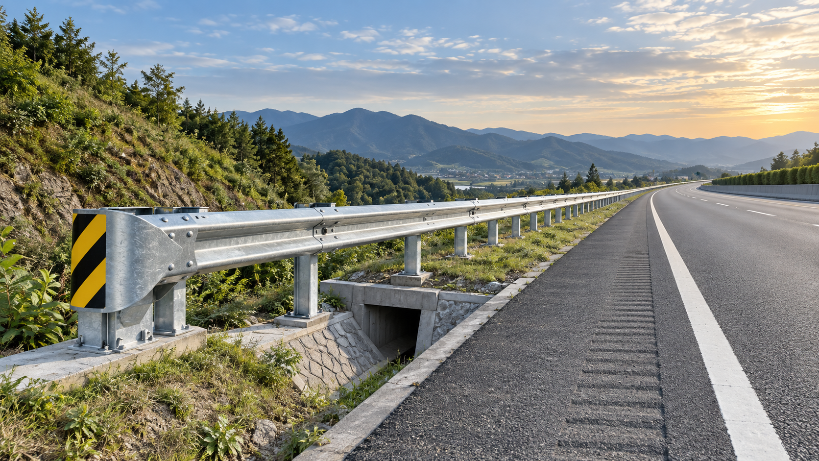
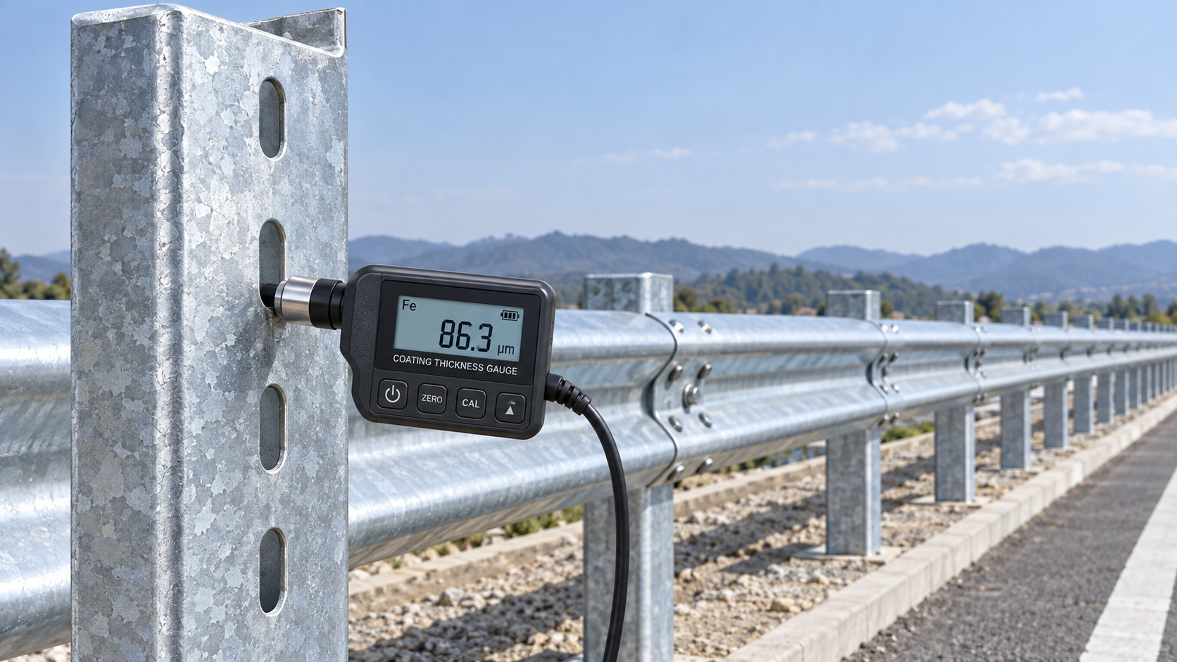
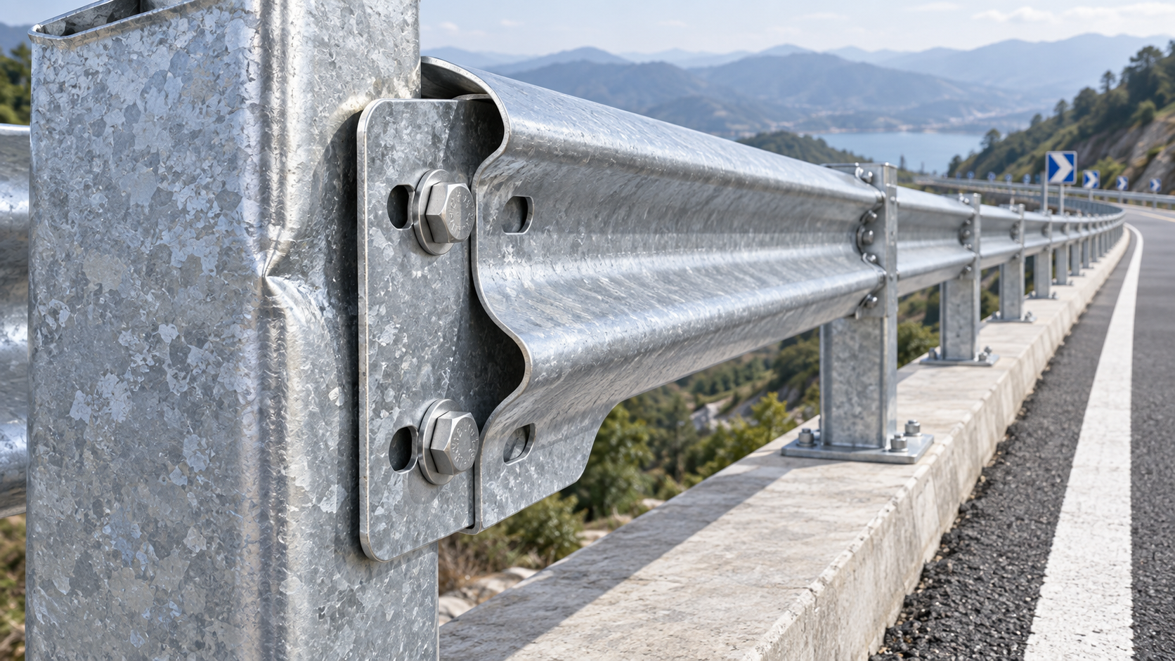
A terminal that is too short, too close to a hazard, or installed outside its tested layout can leave an exposed roadside condition even when the W Beam Guardrail run itself appears correct. This often becomes visible during a design review or site inspection: the rail shields a culvert, slope break, fixed object, or bridge approach, but the terminal begins before the required protection length has been achieved.
The practical answer is that terminal length must be selected as part of a tested guardrail system and a verified length-of-need calculation. It should not be chosen simply because a shorter terminal fits the available space. Start by locating the hazard, defining the portion of the hazard that must be shielded, checking the available approach distance and grading, and then selecting a terminal configuration approved for the intended W Beam Guardrail system, post arrangement, rail height, and installation conditions.
Separate terminal length from the length of need
These two dimensions are related, but they solve different problems. The length of need is the section of barrier required to prevent a vehicle from reaching the hazard. Terminal length is the distance required for the end treatment to function as designed when struck from an approach direction.
A guardrail line can fail its safety purpose in two opposite ways. If the length of need is too short, a vehicle may pass behind the rail and reach the hazard. If the terminal is shortened or moved without checking its tested configuration, the end treatment may not manage impact energy or redirect a vehicle in the intended manner. A drawing that shows a hazard, a run of rail, and an end point without clearly identifying both dimensions should be reviewed before fabrication or installation.
For each approach direction, identify:
- the hazard face, edge, or area that requires shielding;
- the expected vehicle path relative to the roadway and shoulder;
- the point at which a vehicle could reasonably travel behind the barrier;
- the beginning and end of the required barrier protection zone;
- the terminal model and its full tested length;
- the transition details where the terminal joins the standard rail run.
On divided roads, ramps, curves, and two-way facilities, this assessment may need to be made from more than one traffic direction. A terminal arrangement that is acceptable for a one-direction approach may not protect traffic approaching from the reverse direction.
Begin with the hazard, not the available space
A constrained roadside frequently creates pressure to select the shortest available terminal. The more reliable sequence is to first assess the hazard and its position, then determine whether the site can accommodate a compliant end treatment. If space is insufficient, the answer may be to extend the guardrail, relocate the terminal, alter the roadside grading, remove or modify the hazard, or use another approved treatment that suits the site constraints.
Hazard type affects how conservatively the layout should be assessed. Fixed objects such as bridge parapet ends, sign supports not designed to be breakaway, utility structures, drainage headwalls, retaining walls, and large trees can create concentrated impact risks. Steep embankments, drop-offs, water, or abrupt ditch geometry may require protection over a broader area because the vehicle path is less predictable after departure from the travel lane.
Check the lateral offset between the hazard and the rail as well. A barrier placed too far from the hazard can allow excessive deflection or vehicle movement before the hazard is cleared. A barrier placed too close may create installation difficulties, prevent proper post embedment, or leave no workable recovery area. Terminal selection cannot correct an inadequate barrier-to-hazard relationship.
Conditions that influence terminal length selection
Approach speed and traffic exposure
Higher operating speeds generally demand greater attention to terminal performance, available runout distance, and the consequences of an end-on strike. Traffic volume, vehicle mix, roadway alignment, and the likelihood of errant vehicles departing the roadway all affect the exposure assessment. The selected terminal must match the applicable project requirements and the approved test level or performance criteria for that road.
Do not assume that a terminal used successfully on a lower-speed access road can be transferred unchanged to a higher-speed mainline. Its suitability depends on the complete approved system, not only on its visible rail shape.
Road alignment and terminal orientation
Horizontal curves, tapering shoulders, intersections, driveway openings, and lane transitions can alter the likely impact angle. A terminal placed on the outside of a curve may be exposed to different departure paths than one on a straight section. The rail line should follow the approved geometry for the selected end treatment. Field adjustments made to avoid a drain, fence, or utility marker can unintentionally change flare, rail height, post spacing, or anchorage alignment.
Where a flared layout is permitted, the flare rate must remain within the limits of the terminal design and project criteria. A flare is not automatically safer because it moves the terminal farther from traffic; an excessive or unapproved flare can affect impact behavior and create an undesirable approach angle.
Embankment and ground conditions
The ground around a terminal is part of the installation, not a secondary landscaping detail. Slopes, curbs, ditches, soft shoulders, erosion, drainage outlets, and uneven grading can change vehicle approach conditions and interfere with post support. Review whether the terminal lies within a recoverable area and whether the roadside surface is stable enough to maintain its intended geometry.
Post foundations require particular attention where drainage causes saturation, where fill is poorly compacted, or where rock prevents the required embedment. Substituting post length, reducing embedment, or cutting posts around underground obstructions should not be treated as a routine site fix. Such changes may alter the system response and need design confirmation.
Verify the tested terminal configuration
W Beam Guardrail terminals are assembled systems. Their performance depends on the interaction of rail sections, end hardware, posts, soil support, rail height, blockouts or energy-absorbing components, bolt locations, anchor details, and spacing. A terminal length shown in a supplier catalogue is meaningful only when the associated components and installation geometry are retained.
Quality review should compare the installation drawings, bill of materials, terminal manufacturer instructions, and applicable road authority requirements before work begins. During inspection, verify the installed system rather than only measuring the overall rail length. A terminal can have the correct total length while still being nonconforming because a critical post is misplaced, a bolt pattern differs, the rail is mounted at the wrong height, or a required energy-absorbing component is missing.
A workable review sequence before release to site
- Mark the hazard limits. Define the area that must not be reachable by an errant vehicle, including the upstream face or leading edge most exposed to traffic.
- Establish the protection run. Determine the length of need from roadway geometry, approach direction, offset, and anticipated departure path under the project’s governing design method.
- Select the end-treatment family. Choose a terminal suitable for the road conditions and compatible with the specified W-beam system.
- Reserve its full installation envelope. Include terminal length, post locations, grading area, access for installation, and any required clear space around the treatment.
- Check the transition. Confirm rail continuity, height, splice orientation, post spacing changes, and connection details between the terminal and the standard guardrail run.
- Review site conflicts early. Drainage pipes, utility corridors, rock, pavement limits, curbs, and slope changes should be resolved before posts are driven or foundations are prepared.
- Inspect against approved details. Record rail height, post positions, terminal dimensions, hardware, galvanizing condition, and surrounding grade before acceptance.
Support details can affect the terminal decision
Where the approved drawings require base-supported or specially configured posts, the support component must transfer loads without allowing significant movement of the barrier line. A U Post Base Plate may be specified for highway guardrail systems where the design calls for vertical support and load transfer through an appropriate foundation connection. Available C-type, U-type, Z-type, and H-type arrangements should be selected only to match the approved post and foundation detail.
Spacing also matters beyond the terminal itself. Standard post spacing may be 4 meters, while critical locations can require 2-meter spacing according to the applicable design. Hot-dip galvanizing supports corrosion resistance in exposed roadside environments, but it does not compensate for incorrect spacing, insufficient foundation capacity, or a changed terminal layout. When non-standard post diameter, wall thickness, or length is required by site conditions, the change should remain aligned with the engineered system detail.
Installation findings that should trigger a re-check
Several field conditions deserve immediate attention because they can invalidate an otherwise reasonable terminal selection. These include a terminal ending beside a steep slope, a post installed in loose backfill, a rail line that has been shifted toward traffic to avoid an obstacle, standing water around terminal posts, or a terminal nose that falls outside the planned clear area. Damage from handling, distorted rail sections, missing caps, and coating loss at cut or drilled areas should also be addressed before handover.
A shortened terminal should never be accepted merely because the rail still reaches the hazard. Likewise, extending a terminal with extra rail does not automatically create a compliant arrangement. The governing question is whether the installed end treatment, its support conditions, and its connection to the W Beam Guardrail remain consistent with the approved design and required roadside safety performance.
Where the site cannot maintain the required terminal geometry, post support, grading, or length of need, pause the installation and obtain a revised approved layout. That decision is usually less disruptive before final drilling, galvanizing repair, or post installation than after the roadside barrier has been accepted for service.
Leave A Reply
Need More Details?
Contact me for details on creating and managing design projects, project features, and services and prices
consult
Our company was established in 1998. It‘s a Chinese pioneer enterprise integrating production and sales, committed to providing high-quality steel products to customers at home and abroad.

First class quality service and professional after-sales team.
Get in Touch
*We respect your confidentiality and all information are protected.