






NEWS
Categories List

Start with the impact level, not the rail profile
When a Guardrail selection goes wrong, the problem usually starts early: the team chooses a familiar barrier layout before confirming the containment demand. For technical evaluators, that order should be reversed. Containment level tells you what kind of vehicle impact the system is intended to manage under the relevant test regime. Deflection rating tells you how much room the barrier needs to work during impact. Road design sits between those two facts.
If you treat containment as a paperwork item and deflection as a shop detail, you can end up with a compliant drawing that still performs badly on site. A narrow shoulder, a bridge edge, a steep embankment, a sign foundation, or a drainage structure can all turn an acceptable barrier into the wrong one. The practical check is simple: first confirm the required containment class from the project documents and governing standard, then verify whether the available working space can absorb the system’s movement without secondary hazards.
What to check before you compare systems
- Vehicle mix and road function. A low-speed access road, a rural highway, and a freight-heavy corridor do not present the same risk. The design file should already define the target performance level. Your job is to verify that the proposed barrier matches that requirement and is not simply a stock section carried over from another package.
- Available lateral space. This is where deflection rating becomes decisive. Look behind the rail line: bridge parapets, lighting columns, culvert heads, retaining walls, utility chambers, and slope breaks all matter. If the barrier needs more dynamic movement than the site allows, the nominal containment level alone does not solve the problem.
- Soil and foundation condition. Post-supported systems depend on how impact load is transferred into the ground. Soft shoulders, filled ground, erosion-prone edges, or buried obstructions can change real behavior even when the rail beam itself is correct.
- Transitions and terminals. Evaluators often review the main run carefully and then lose performance at the connection points. A system is only as reliable as its weakest transition.
Containment level answers one question; deflection answers the next one
Containment is about the barrier’s capacity to redirect and contain an impacting vehicle within the tested conditions defined by the applicable standard. That tells you whether the system is suitable for the risk environment. It does not tell you whether it can be installed safely in a tight corridor.
Deflection, or the movement of the barrier during impact, is where geometry, maintenance clearance, and nearby objects enter the decision. A higher-containment system can still be a poor fit if it needs more working width than the project provides. On the other hand, reducing deflection by tightening post spacing or changing the support layout may affect cost, constructability, and sometimes repair severity after impact. That is why experienced reviewers do not ask, “Which barrier is stronger?” They ask, “Which tested system meets the required containment and still works within this exact roadside envelope?”
A field-minded checklist for evaluating the layout
- Read the standard reference on the drawing set. Do not assume one market’s barrier classification maps neatly onto another. Check the specified performance class in the contract documents, approval sheets, or test-backed product submittals.
- Measure the real working zone, not just the shoulder width. Include offsets to rigid obstacles, edge drop-offs, drainage features, and utility interfaces. This is the dimension that decides whether the barrier can deflect safely.
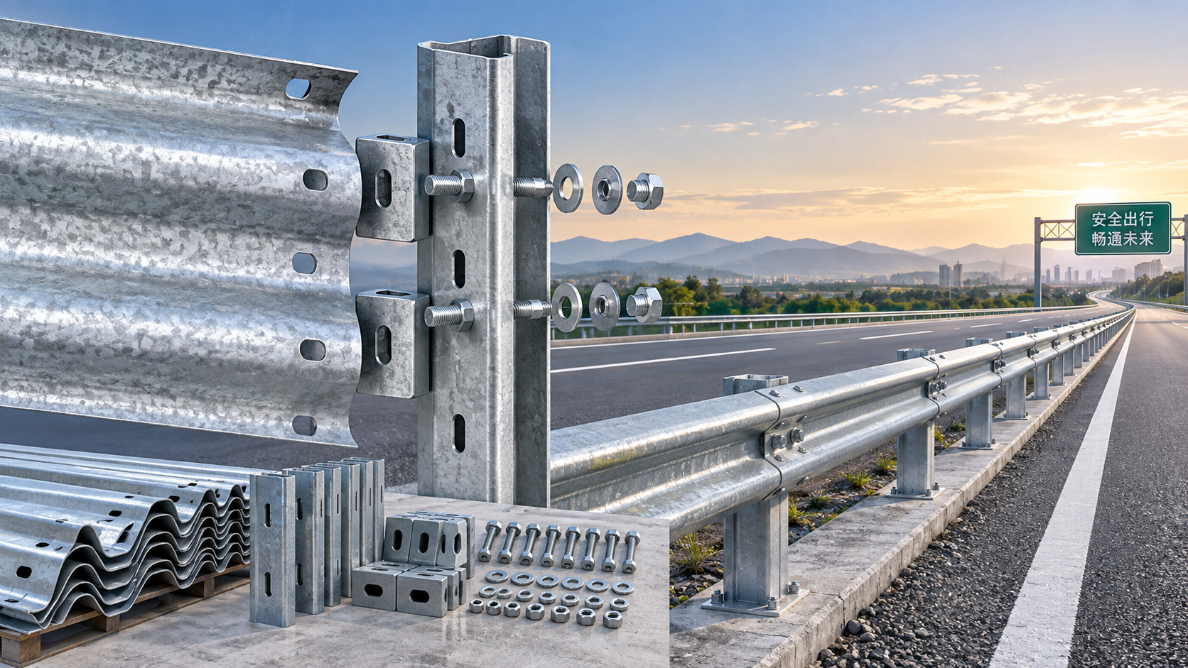
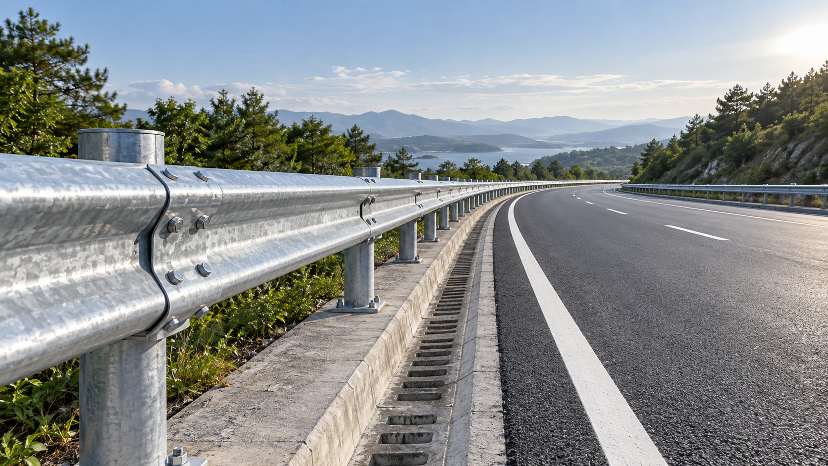
- Review post spacing against the risk point. In highway guardrail systems, support members do more than hold the beam upright. They control load transfer into the foundation and help prevent excessive overturning or lateral shift. For example, Z Post arrangements may be set at 4 meters in standard runs and tightened to 2 meters at critical locations, depending on the approved system design and site need.
- Check whether the support type matches the installation condition. C-type, U-type, Z-type, and H-type posts are not interchangeable by convenience. The proposed section has to match the tested or approved configuration, the foundation response, and the detailing around the rail and blockout assembly.
- Look closely at bridge approaches and median constraints. These are common places where evaluators discover too late that a flexible system cannot move without striking another structure.
- Verify corrosion protection and fabrication quality where service life matters. Galvanizing, surface preparation, dimensional control, and inspection discipline affect long-term reliability, especially in exposed roadside environments.
Common evaluation mistakes that lead to redesign
One recurring mistake is treating barrier deflection as uniform across the project. It is not. The same Guardrail system may be acceptable on an open embankment and unsuitable within a constrained interchange ramp. Another is reviewing the rail beam specification while giving too little attention to the posts, blockouts, bolts, and anchorage behavior. In practice, support detailing decides whether impact forces are dispersed properly into the foundation or concentrated in a way that creates local failure.
There is also a purchasing-driven error: selecting a post or accessory because it looks similar to the approved design. Similar is not enough. If the tested system depends on a particular geometry, spacing, connector set, or energy-absorbing component, substitutions have to be checked against the project’s technical basis, not just against nominal dimensions.
Where product details actually matter
For evaluators reviewing steel roadside barriers, the support post is often where design intent meets construction reality. A post system used in highway guardrail applications needs to provide vertical support, transfer impact load into the ground, and keep the barrier line from shifting excessively under load. That is why manufacturing quality matters: drilling accuracy, bending control, surface treatment, non-destructive testing where specified, galvanizing, and coating consistency all affect whether the installed system behaves like the approved one.
In projects with unusual geometry or non-standard roadside constraints, custom fabrication based on project drawings can be the practical route, but only if the evaluator keeps the distinction clear between a custom-manufactured component and a change to the approved performance configuration. The former may be manageable; the latter needs a much harder review.
Use this decision order when time is short
A good review sequence is straightforward: confirm the required containment class, map the available deflection space, inspect the support and spacing arrangement, and then review fabrication and corrosion details. That order keeps the technical decision tied to road geometry and actual impact behavior, which is where most Guardrail problems begin and where solid road design usually gets them under control.
Leave A Reply
Need More Details?
Contact me for details on creating and managing design projects, project features, and services and prices
consult
Our company was established in 1998. It‘s a Chinese pioneer enterprise integrating production and sales, committed to providing high-quality steel products to customers at home and abroad.

First class quality service and professional after-sales team.
Get in Touch
*We respect your confidentiality and all information are protected.