






NEWS
Categories List

When a Highway Safety Barrier System Needs a Rigid-to-Flexible Transition
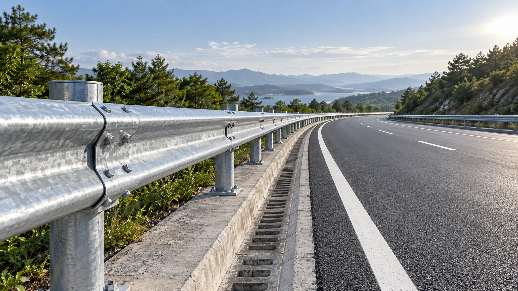
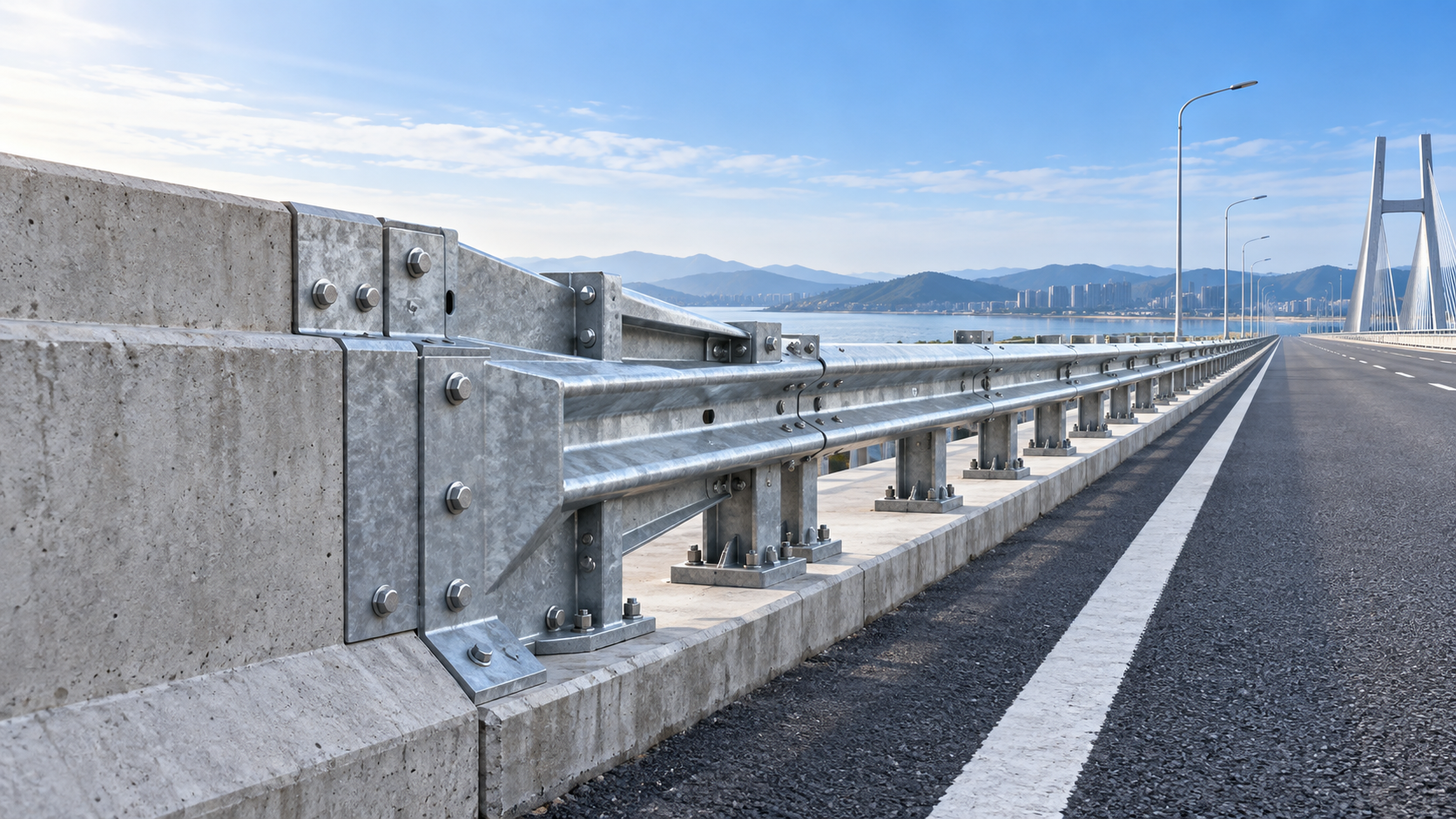
A roadside barrier is not simply a line of steel or concrete placed between traffic and a hazard. It is a controlled energy-management system. That distinction becomes especially important where a rigid concrete barrier meets a flexible steel guardrail. Without a properly engineered connection, the change in stiffness can create one of the most vulnerable points in a Highway Safety Barrier System.
Quality and safety teams often encounter this issue during drawing review, site inspection, or after a design change near a bridge, culvert, median opening, ramp nose, or roadside structure. The layout may look continuous on paper: concrete on one side, guardrail on the other. In a vehicle impact, however, the two barriers respond very differently. Concrete moves very little; a guardrail is intended to deflect, redirect, and absorb part of the impact energy through rail deformation, post yielding, and soil interaction.
A transition is needed when those different responses must be made compatible. It is not an optional strengthening detail added merely because the two systems happen to touch. It is a functional part of the barrier assembly, and it should be treated with the same care as the terminal, anchor, rail splice, post foundation, and concrete interface.
Why the connection point is more critical than it appears
A flexible guardrail can deflect significantly under impact. If it ends abruptly at a rigid parapet or concrete wall, the rail may pocket, snag, tear, or allow the vehicle to strike the rigid object at an unfavorable angle. At the same time, if the first few posts next to the concrete remain too flexible, the rail can be pulled toward the barrier face and lose the intended redirection path.
The practical purpose of a rigid-to-flexible transition is therefore to introduce stiffness gradually. The assembly usually controls rail geometry, post spacing, post type, anchorage, blockouts or offset components, and the connection to the concrete structure. The exact arrangement must come from an approved system design rather than a site-made interpretation of what “looks stronger.” A locally added plate, shorter rail section, or extra weld may alter the load path in ways that were never evaluated.
This is where a common misunderstanding causes trouble: more steel is not automatically a safer transition. An excessively rigid first segment may produce abrupt vehicle deceleration or encourage wheel snagging. A segment that is too weak may fold or pull away. The target is controlled compatibility between two systems, not maximum stiffness at every point.
Situations that normally require transition design review
A transition should be specifically reviewed whenever a semi-rigid or flexible rail terminates at, attaches to, or runs immediately adjacent to a much stiffer roadside feature. Bridge approaches are the most familiar example. A steel guardrail approaching a concrete bridge parapet needs a connection that prevents the rail from deflecting into the parapet edge and helps maintain a continuous containment line.
Other locations deserve the same attention:
- Concrete median barriers connected to steel median guardrails;
- Bridge end sections, retaining walls, culvert headwalls, and drainage structures close to the clear zone;
- Guardrails placed near pier protection zones, lighting pole foundations, or fixed sign supports;
- Ramp divergences and gore areas where impact angles may be less predictable;
- Barrier runs interrupted by maintenance access points or openings in median strips;
- Retrofit work where a new steel rail must connect to an older concrete structure with uncertain embedded details.
Not every visible change in barrier material requires the same transition treatment. The decision depends on the approved crashworthy system, design speed, traffic mix, anticipated impact conditions, barrier offset, available deflection space, and the nature of the hazard behind or beside the barrier. Where a project follows a specific testing or acceptance framework, such as MASH or EN 1317, the transition details should be checked against the applicable project requirements and the system documentation. Components from different manufacturers or unrelated tested configurations should not be assumed interchangeable.
The details inspectors should examine before installation
The first check is continuity. Rail height, lateral alignment, and offset must remain controlled as the system approaches the concrete barrier. A transition can fail in practice even when all parts are present if the rail line rises, drops, twists, or is forced against the concrete face. Small installation deviations matter more here than they do on a long, uninterrupted guardrail run.
The second check is the sequence of stiffness. Approved drawings may specify reduced post spacing, heavier posts, nested or reinforced rail sections, special beams, tubular components, anchor plates, or structural connections to the rigid barrier. These are not isolated items. Their order and orientation are part of the design. Reversing a rail overlap, moving a post to avoid an underground utility, or substituting a standard post because the specified section is unavailable can change how the transition behaves.
The concrete interface needs equally close attention. Inspectors should verify whether anchorage locations, embedment arrangements, bolt grades, hole dimensions, and edge distances match the issued drawings. Drilling into an existing parapet without confirming reinforcement and anchor requirements can create structural concerns as well as barrier-performance concerns. For retrofit projects, the condition of the concrete should be assessed before installation; cracked, spalled, or deteriorated concrete may not provide the support assumed by the transition detail.
There is also a field reality that design documents cannot always eliminate: drainage, pavement overlays, buried services, and uneven shoulders affect post installation. If post depth, soil resistance, or rail height cannot be achieved as detailed, the answer should not be an improvised adjustment. It should trigger an engineering review.
Where high-stiffness steel members can be appropriate
Certain high-risk locations need a more robust intermediate member than a conventional rail segment, particularly where guidance performance and structural stability are tightly constrained. Open-box sections are commonly considered for locations such as bridge sections, median openings, ramp divergences, and areas protecting piers or other fixed hazards. Their value is not simply thickness; a rectangular open-box profile can provide high section modulus and bending stiffness, helping resist bending deformation during an impact.
For example, an Open Box Beam 2.4m manufactured from high-quality hot-rolled steel plate may be specified as part of a suitable system where a stiffened barrier segment is required. Zinc-aluminum-magnesium coating or an appropriate powder coating can also be relevant in aggressive environments, provided the selected coating system, component geometry, and repair requirements match the project specification. A stated long service life in coastal or high-salt-fog exposure still depends on installation quality, damage repair, drainage, and the actual corrosivity of the site.
The important qualification is that a high-stiffness beam should be selected as part of a designed and approved transition arrangement. It is not a universal replacement for W-beam, thrie-beam, or other rail elements. A component may have excellent intrinsic strength yet be unsuitable if its connections, post layout, and end conditions do not create a compatible crash-performance path.
Manufacturing quality is part of barrier performance
Transition components tend to have more fabrication-sensitive features than ordinary rail runs: closely controlled hole patterns, bends, reinforced sections, special brackets, connection plates, and sometimes welded assemblies. A few millimeters of hole misalignment can force field reaming or unintended bolt loading. Poorly formed bends can affect rail alignment. Inconsistent galvanizing or inadequate preparation around cut edges and welded areas can shorten durability where moisture and de-icing salts are present.
For this reason, quality control should begin before delivery. The review should cover material traceability where required, dimensional checks against approved drawings, hole position and diameter, weld inspection requirements, surface preparation, coating thickness requirements, and packing methods that prevent distortion in transit. Depending on the component and project specification, manufacturing may involve drilling, bending, rust removal, shot peening, non-destructive testing, galvanizing, and painting. The process matters because a well-designed transition can still be compromised by poor repeatability in fabrication.
It is also worth separating design responsibility from manufacturing responsibility. A capable manufacturer can manufacture to supplied drawings, assist with design development, and coordinate quotation, production, and installation requirements. But the final barrier configuration must remain consistent with the project’s approved safety design. “Custom-made” should never mean “untested and undocumented.”
A practical acceptance mindset
During final inspection, it helps to walk the transition in the direction a vehicle would travel. Look for exposed edges, abrupt rail offsets, gaps at the concrete connection, protruding bolt ends, unsupported rail ends, damaged coating, and post locations that differ from the drawing. Then review the opposite traffic direction where the barrier is bidirectional or where reverse-direction impacts are credible. A transition that appears acceptable from one approach can present a different geometry from the other.
The best time to resolve a rigid-to-flexible interface is before steel is fabricated and before concrete anchors are drilled. Once rail, posts, pavement, utilities, and bridge works overlap, small omissions become expensive to correct. For a Highway Safety Barrier System, the transition should be reviewed as a complete assembly: hazard, barrier type, deflection behavior, connection detail, fabrication tolerances, installation conditions, and maintenance access. That is the level at which roadside safety is actually decided.
Leave A Reply
Need More Details?
Contact me for details on creating and managing design projects, project features, and services and prices
consult
Our company was established in 1998. It‘s a Chinese pioneer enterprise integrating production and sales, committed to providing high-quality steel products to customers at home and abroad.

First class quality service and professional after-sales team.
Get in Touch
*We respect your confidentiality and all information are protected.