






NEWS
Categories List
Guardrail End Treatments Explained: Choosing Designs for Roadside Impact Risks
Selecting a Guardrail End Treatment is not a finishing detail at the end of a roadside barrier design. It is a crash-performance decision. The rail may perform well along its length, but its terminal can become the most exposed part of the system if the approach angle, available runout area, traffic direction, or site geometry has been misunderstood.
For technical assessors, the practical question is rarely “Which terminal is best?” It is “Which terminal behavior is appropriate for this hazard, this barrier system, and this impact path?” A solution that is reasonable on a straight rural shoulder may be unsuitable at a ramp gore, bridge transition, median opening, or constrained urban corridor.
The starting point is to consider the end treatment and the guardrail as one tested and compatible assembly. Rail profile, post type and spacing, anchorage arrangement, soil condition, transition details, and installation geometry all influence how energy is managed during a collision. Mixing components from visually similar systems without confirming compatibility is a recurring source of risk.
What an End Treatment Must Do in a Real Impact
A guardrail terminal must address more than a head-on strike. Vehicles can approach it nearly parallel to the rail, at a shallow angle from the traffic side, from the reverse direction, or after leaving the roadway in a secondary event. The expected impact conditions should be reviewed before selecting the design, rather than after a standard layout has already been copied into the drawing package.
Depending on its design and approved application, an end treatment may dissipate energy through controlled deformation, redirect an errant vehicle, or create an anchoring condition that allows the adjacent rail to develop its intended tensile behavior. These functions are different. A terminal intended to absorb energy in an end-on impact should not be casually treated as a substitute for a robust transition at a fixed object.
The assessor should also distinguish between a terminal installed because a rail physically has to end and one installed because the terminal itself is likely to be struck. Those are not always the same design situation. At a low-exposure end located outside the practical recovery area, the priority may be system continuity and maintainability. At a high-speed divergence or median opening, impact performance and guidance behavior usually deserve much closer scrutiny.
The Main Design Choices—and Where They Can Go Wrong
Energy-absorbing terminals are commonly considered where an end-on impact is credible. Their operation depends on the specified rail, hardware, anchorage, and clear space around the terminal. A common mistake is to evaluate only the terminal head while overlooking obstructions beside it: drainage structures, sign supports, exposed foundations, or raised curbs can alter vehicle behavior before the terminal can perform as intended.
Flared terminals move the rail end away from the traffic path. They can reduce the likelihood of a direct end-on hit where space permits, but the flare itself needs review. A sharp flare in a constrained corridor can introduce snagging concerns, reduce usable shoulder width, or place the terminal closer to another roadside object. The available offset is useful only when it creates a genuinely more forgiving path.
Buried or turned-down rail ends are sometimes encountered in legacy installations, but they should not be assumed to provide equivalent behavior to modern tested terminal systems. Their suitability depends on applicable project requirements and current local acceptance criteria. Technical reviewers should avoid approving a familiar detail solely because it has been used historically.
Anchored terminals serve a different purpose again. At a bridge approach, for example, the barrier must transition into a stiffer structural condition without creating a pocketing or snagging point. The end condition, rail transition, post stiffness, and connection to the bridge-side protection should be assessed together. Treating each drawing detail as independent can hide a weak point exactly where impact loads change abruptly.
Start with the Site, Not the Catalogue
A useful evaluation begins with the vehicle’s likely departure path. Roadway speed, horizontal curvature, crossfall, slope, lane configuration, and opposing traffic all affect that path. A terminal on the outside of a curve can face a very different exposure from one placed on a straight tangent, even when both are attached to the same rail type.
The following questions usually reveal whether a proposed Guardrail End Treatment has been selected thoughtfully:
- Is an end-on impact plausible from the direction of approaching traffic?
- Can a vehicle reach the terminal at a shallow angle and be safely redirected?
- Is there adequate space for the terminal’s intended deformation or movement?
- Does the terminal connect to the exact rail, post, and anchorage configuration for which it is intended?
- Are curbs, drains, utility cabinets, poles, slopes, or bridge elements likely to interfere with crash behavior?
- Will maintenance crews be able to inspect and replace damaged components without compromising the rest of the run?
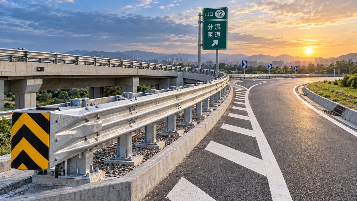
This review is especially important in high-risk locations such as ramp divergences, expressway median openings, pier protection zones, and bridge sections. These areas often combine limited space with hard objects and more complex impact angles. A compact layout may look efficient on plan, yet leave no room for a terminal to function as intended.
System Stiffness Matters Near Critical Hazards
Not every location benefits from the same level of rail stiffness. Where the barrier is protecting a vulnerable fixed object or needs to limit deflection near a constrained hazard, assessors may need a more rigid structural solution than a standard roadside run. The key is not simply choosing “stronger” steel; it is confirming that higher stiffness fits the overall crash-performance design and does not create an incompatible transition.
For example, an open-box beam may be considered in locations requiring strong guidance and limited deformation, including bridge sections, pier zones, and selected median or ramp applications. The Open Box Beam 2.4m uses a rectangular open-box section formed from high-quality hot-rolled steel plate, with high section modulus and bending stiffness. Its value is not that it replaces a terminal; rather, it can form part of a more resistant barrier arrangement where the adjacent hazard leaves little tolerance for rail movement.
That distinction matters. A stiff beam section installed beside a terminal does not automatically make the terminal safer. Connection detailing, stiffness changes, post behavior, and the transition length all require review. Abrupt changes in barrier response are often where otherwise sound components stop behaving as a coherent system.
Manufacturing and Installation Checks Are Part of Selection
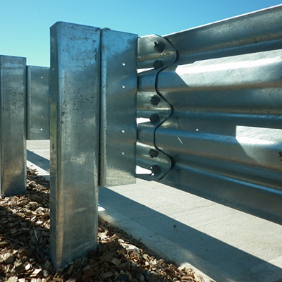
A terminal design can be technically appropriate and still underperform if fabricated or installed with poor dimensional control. Hole positions, rail curvature, cut lengths, bolt interfaces, galvanizing quality, and post alignment affect fit-up in the field. This is why technical review should extend beyond drawings to fabrication capability and inspection procedures.
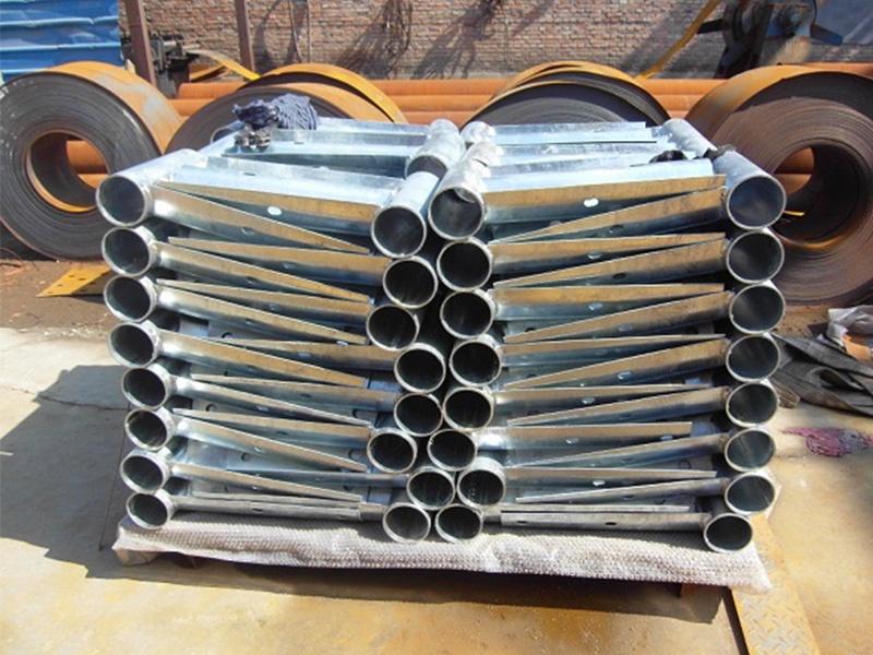
For steel guardrail systems, the manufacturing route may include drilling, bending, surface preparation, shot peening where specified, non-destructive testing where applicable, galvanizing, and protective painting. The required sequence depends on the product and project specification. In coastal or high-salt-fog environments, coating selection deserves early attention; zinc-aluminum-magnesium coatings or suitable powder-coating systems may be considered where project requirements call for additional corrosion resistance or visual warning colours.
Installation quality is equally practical. A terminal installed at the wrong height, on unsuitable ground, with substituted bolts, or with a shortened run-up section may no longer reflect its intended configuration. Field crews need clear, component-specific installation information, especially where the barrier changes from standard rail to a terminal, transition, or high-stiffness beam section.
A Defensible Selection Record
For design reviews and procurement decisions, the most defensible record is a short but specific rationale: the roadside hazard being shielded, expected impact exposure, applicable project standard, selected barrier family, terminal configuration, required clear area, and any installation limitations. Include confirmation that the proposed components are compatible, rather than merely available from the same supplier.
The best Guardrail End Treatment is usually the one that fits the actual crash path and the tested barrier arrangement without forcing compromises in geometry, clearance, or maintenance access. If the site cannot accommodate the terminal’s operating space, the answer is often to revisit the barrier layout—not to hope that a smaller or improvised end detail will solve the problem.
Leave A Reply
Need More Details?
Contact me for details on creating and managing design projects, project features, and services and prices
consult
Our company was established in 1998. It‘s a Chinese pioneer enterprise integrating production and sales, committed to providing high-quality steel products to customers at home and abroad.

First class quality service and professional after-sales team.
Get in Touch
*We respect your confidentiality and all information are protected.