






Categories List
Recent Posts
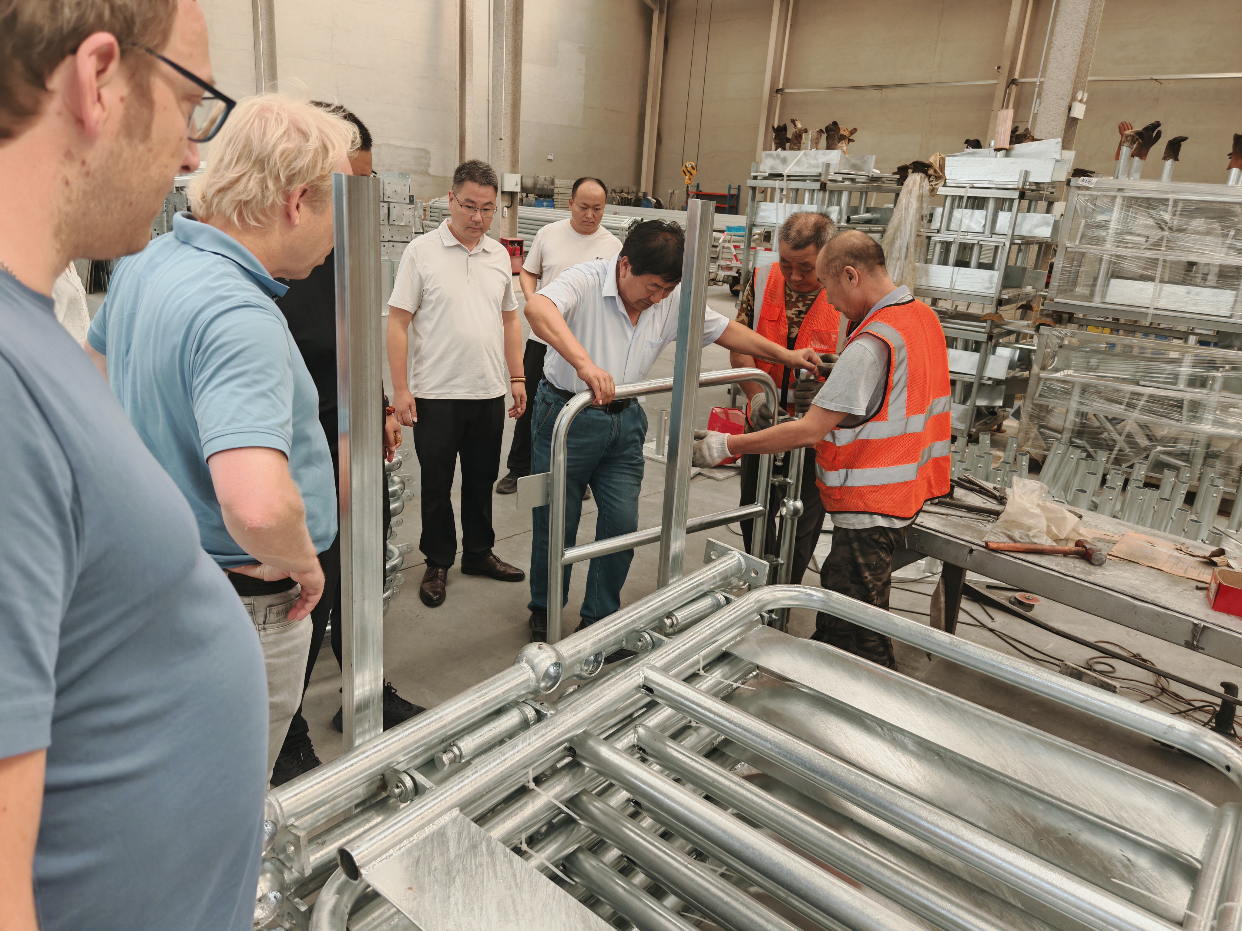
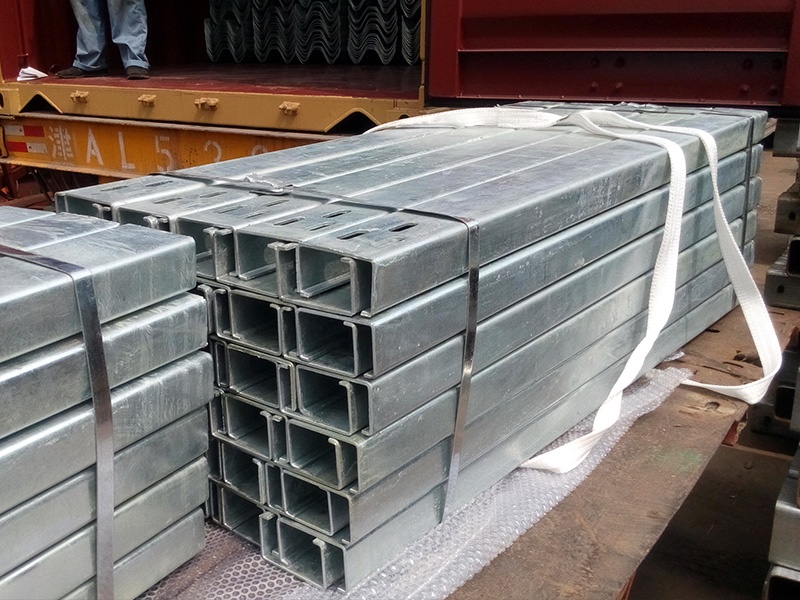
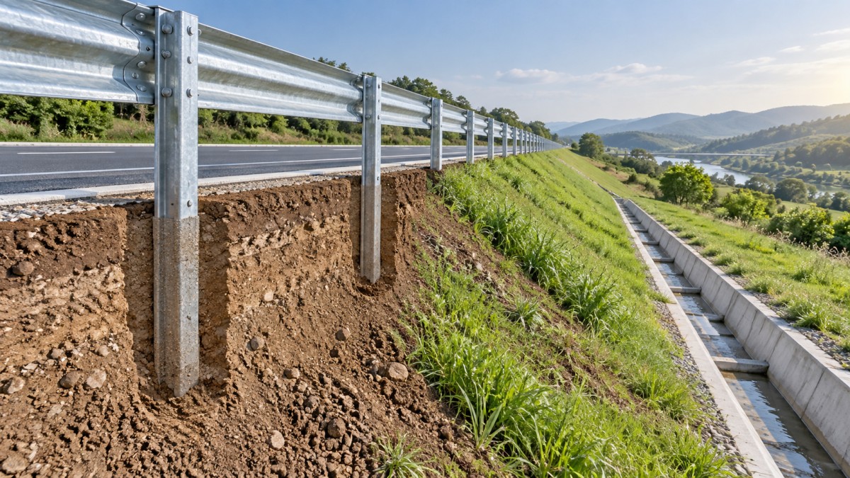
On an embankment, a guardrail line can look straightforward until the support posts meet variable ground: compact fill near the shoulder, softer material lower on the slope, a drainage trench behind the rail, or a widening that leaves little room for driving equipment. In these conditions, choosing a post only by its nominal size can produce a system that is difficult to install, poorly aligned, or unable to develop the support assumed by the barrier design.
C Posts are suitable for many embankment guardrail applications when the soil can provide dependable lateral and vertical restraint, the post installation depth can be achieved without undermining the slope, and the complete barrier system has been designed and tested around that post type. They are less suitable where fill is loose or highly variable, erosion is active, buried obstructions prevent consistent embedment, or a narrow slope crest leaves inadequate space behind the rail. The decision should begin with the embankment condition, not with the post profile alone.
Start with the ground that will resist the post
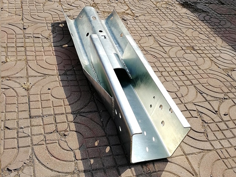
A C-shaped steel post transfers guardrail loads into the surrounding soil through its embedded length and flange geometry. The post may be structurally sound, but its performance still depends on whether the soil around it can mobilize resistance without excessive displacement. This is especially relevant at embankment edges, where the ground may consist of placed fill rather than uniform native material.
Firm, well-compacted granular or cohesive fill generally offers a more predictable setting for driven C Posts. The installer can achieve a repeatable penetration depth, and the post has sufficient surrounding material to resist rotation during an impact. A stable embankment crest with a reasonably level working strip also helps maintain spacing, rail height, and post plumbness.
Conditions become less reliable when the upper embankment layer is loose, recently placed, saturated, or mixed with oversized rock. In soft fill, a post may drive easily but lack the lateral restraint needed under load. In rocky fill, the opposite problem occurs: the post can refuse early, twist, or sustain damage during driving. Neither outcome should be corrected simply by forcing the post to the target depth; the cause of refusal or low resistance must be understood first.
How slope geometry changes the decision
The slope itself affects both installation and barrier behavior. A post positioned near a crest has less retained soil on the traffic-side or slope-side than a post placed on broad, level ground. As the slope becomes steeper or the available shoulder becomes narrower, the soil mass supporting the post can reduce. The risk is not limited to post movement. Construction activity may disturb the crest, create ruts that direct water toward the rail line, or loosen material that later erodes.
Where the embankment has a broad, stable top and a gradual slope, a driven C-post arrangement is often practical, provided the required post depth and set-back can be maintained. A moderate slope does not automatically rule out its use. The key question is whether enough undisturbed material remains around and below each post after installation.
A steep slope, a sharp crest break, or a slope already showing sloughing deserves a more cautious review. Moving the rail line farther from the edge may improve support, but it can also alter the roadside clearance and barrier placement. Shortening the post because of a difficult slope is not a neutral adjustment; it changes the embedded restraint and should only be done where the system design specifically permits it.
Drainage is often the hidden limitation
Water changes embankment conditions more quickly than visible surface appearance suggests. A location may be firm during layout yet lose strength after repeated wetting, seepage from an adjacent ditch, or runoff concentrated at post holes and disturbed soil. C Posts installed along a drainage path can be exposed to scour around the base, corrosion risks associated with persistent moisture, and progressive settlement of the shoulder.
Before selecting the support arrangement, identify where water travels during and after rain. Look for outlet structures, ditch transitions, culvert ends, low points behind the guardrail, and erosion repairs. A shallow swale cut too close to the posts can reduce the supporting soil wedge. Likewise, backfilling around a post in a wet or poorly compacted area may create a weak local zone even when the surrounding embankment is sound.
Where drainage cannot be moved, the design may require a different post foundation approach, local stabilization, revised barrier placement, or a detail that keeps runoff away from the support zone. Coating and galvanizing protect the steel surface, but they do not solve loss of soil support caused by washout.
Match the post to the approved barrier configuration
It is tempting to treat the post as an interchangeable component beneath a rail beam. That approach can be unsafe. Post shape, steel thickness, spacing, blockout arrangement, rail height, terminal treatment, and soil condition work together. A C section may be appropriate in one guardrail configuration and inappropriate in another even when the rail beam appears similar.
Review the proposed arrangement as a complete assembly. Confirm the intended spacing and the connection details between post, blockout, and rail. Check whether the barrier needs to accommodate a transition to a bridge rail, culvert headwall, retaining structure, or terminal. These locations can introduce stiffer supports or abrupt changes in deflection behavior, so substituting a C post for another profile without design confirmation can create a weak transition rather than a cost-saving simplification.
Installation constraints can reveal a poor selection early
A post that is theoretically suitable may still be impractical to install in a constrained roadside corridor. Driving equipment needs stable access and enough working room to keep the post vertical. On a narrow shoulder, machinery operating close to the embankment edge can disturb the very ground that the post depends on. Repeated repositioning can also leave uneven post elevations or misaligned rail slots.
Set out the line before production and verify conflicts with utilities, drainage components, sign foundations, existing pavement edges, and buried rock. When a post encounters refusal, the crew should record the depth and location rather than make an unapproved field substitution. Localized refusal may indicate rock; repeated shallow refusal may show a continuous obstruction or an unsuitable installation method. Field observations are useful inputs for deciding whether the design needs adjustment.
Manufacturing quality also matters where site conditions are demanding. Consistent drilling and bending support correct assembly, while rust removal, shot peening, non-destructive testing where specified, galvanizing, and painting can be incorporated according to project requirements. However, fabrication controls should support the selected design rather than compensate for unsuitable embankment geometry or weak soil.
Use impact and deflection needs to test the choice
Containment requirements should be considered alongside ground conditions. A roadside with limited clear space beyond the guardrail may have little tolerance for excessive deflection. Yet making the support arrangement stiffer without considering the approved system can alter how loads are distributed through posts and rail elements. The appropriate question is not whether a C profile is “strong enough” in isolation, but whether the installed system can perform as intended at that location.
Special locations deserve closer review: the approach to a rigid structure, an embankment above a watercourse, a road section with a drop-off beyond the rail, or an area where slope erosion could expose post embedment over time. Accessories that manage movement or component interaction may be relevant in certain assemblies; where the specified design calls for such an accessory, Spring Steel Buffers can be considered as part of the defined connection or protection detail. They should not be treated as a substitute for adequate post support or proper barrier geometry.
A practical review before committing to C Posts
Begin with available geotechnical and roadway information, then inspect the proposed rail line for visible changes in fill, slope shape, drainage, and access. Confirm the required embedment can be achieved at every post location without placing the rail too close to the edge. Next, compare the proposed post with the barrier system drawings, including spacing, rail elevation, blockouts, terminals, and transitions. Finally, establish a field response for refusal, soft ground, damaged coatings, and unexpected utilities before installation begins.
C Posts are a sound choice on stable embankments with adequate soil confinement and a compatible guardrail design. They become a poor choice when the project relies on uncertain fill, ignores drainage, or assumes that a driven post can solve a slope stability problem. Resolving those limits during evaluation is far less disruptive than correcting a misaligned or inadequately supported guardrail after the rail has been installed.
Leave A Reply
Need More Details?
Contact me for details on creating and managing design projects, project features, and services and prices
consult
Our company was established in 1998. It‘s a Chinese pioneer enterprise integrating production and sales, committed to providing high-quality steel products to customers at home and abroad.

First class quality service and professional after-sales team.
Get in Touch
*We respect your confidentiality and all information are protected.