






NEWS
Categories List
Impact Attenuator Selection for Fixed Roadside Obstacles and Narrow Medians
Selecting the right Impact Attenuator for fixed roadside obstacles and narrow medians is critical to protecting road users, meeting specifications, and controlling long-term project costs.
For project managers, compliance alone is insufficient. The selected system must match site geometry, expected impact conditions, installation constraints, maintenance access, and the owner’s lifecycle objectives.
Start With the Hazard, Not the Product Catalog
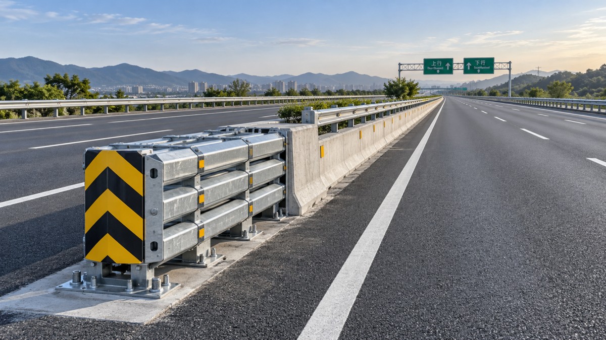
An Impact Attenuator should be selected after the roadside hazard has been clearly defined, including its location, rigidity, exposure, approach angle, and available recovery space.
Fixed obstacles include bridge piers, sign supports, toll structures, retaining-wall ends, concrete barriers, lighting poles, utility cabinets, and terminal ends of roadside safety systems.
Narrow medians create additional risk because vehicles may have limited room to recover, redirect, or decelerate before reaching opposing traffic or a rigid structure.
Project teams should first determine whether the primary risk is head-on impact, angled impact, side impact, vehicle penetration, rollover, or secondary collision with adjacent infrastructure.
This hazard-based approach avoids a common procurement mistake: selecting a familiar product type before confirming whether its tested performance envelope matches actual site conditions.
Documenting the hazard also improves coordination between roadway designers, safety engineers, maintenance teams, contractors, and asset owners during later approval and installation stages.
Confirm the Required Crash Performance Level
The required crashworthiness level should be based on governing roadway standards, design speed, traffic volume, vehicle mix, obstacle severity, and the consequences of system failure.
A suitable Impact Attenuator must be tested and approved for the applicable performance criteria, including impact speed, vehicle mass, impact angle, occupant risk, and post-impact behavior.
Project managers should request complete test documentation instead of relying only on a general compliance statement or a supplier’s product brochure.
Testing records should identify the exact system configuration, including foundation details, module arrangement, anchorage components, transition sections, and any required backup structure.
Small field changes can affect crash performance. Substituting bolts, reducing installation length, altering grading, or modifying a transition may invalidate the intended safety function.
Where heavy trucks, buses, construction traffic, or unusually high operating speeds are present, the project team should assess whether standard passenger-vehicle assumptions remain adequate.
Evaluate Available Length and Median Geometry
Available installation length is often the decisive factor in narrow median applications. Energy absorption requires physical space, and compact systems may involve different maintenance or replacement demands.
Measure the usable length from the hazard face to upstream constraints, including drainage structures, bridge joints, barrier transitions, access roads, utility covers, and maintenance clear zones.
Also review width, cross slope, pavement condition, shoulder dimensions, curb placement, and drainage paths because these conditions affect both installation feasibility and vehicle interaction.
A system that fits on a plan drawing may become impractical when construction tolerances, inspection access, snow storage, or resurfacing requirements are considered.
For constrained sites, the best decision is frequently a coordinated solution involving barrier alignment, obstacle shielding, grading modification, and attenuation rather than an attenuator alone.
Early geometric review reduces costly redesigns after procurement, especially where foundations, utility relocations, bridge approaches, or median drainage improvements have long lead times.
Understand Redirective and Non-Redirective Behavior
Impact attenuation systems differ in how they manage vehicles striking the nose or sides of the installation. This distinction has direct consequences for narrow medians and adjacent traffic.
Non-redirective systems primarily absorb energy during head-on impacts. They can be effective where impact angles are controlled and sufficient clear space exists around the device.
Redirective systems are designed to manage certain side or angled impacts while reducing the probability that an errant vehicle will penetrate beyond the protected area.
However, redirective behavior should never be assumed from appearance. It must be supported by the tested configuration and compatible with the barrier system connected behind it.
For medians separating opposing traffic, the risk of a deflected vehicle entering another travel lane deserves particular attention during safety review and stakeholder approval.
Project managers should ask engineers to model likely approach paths, especially near ramp diverges, lane drops, curve transitions, bridge sections, and areas with changing lane widths.
Specify the Supporting Structure and Connection Details
An Impact Attenuator is only as reliable as the structure supporting it. The protected obstacle, foundation, barrier transition, and anchorage arrangement must work as one system.
Rigid obstacles can create severe load demands at the rear of the device, while flexible or incomplete support structures may allow excessive movement during a collision.
Steel components should be specified for the expected loading environment, including repeated vibration, corrosion exposure, drainage conditions, debris accumulation, and maintenance activity.
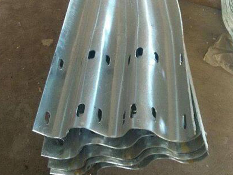
In critical guidance locations, high-stiffness steel components can improve structural continuity. A Hanging Plate may support stronger resistance to bending deformation within compatible highway safety assemblies.
High-quality hot-rolled steel plates with zinc-aluminum-magnesium or powder-coated finishes can provide useful durability where coastal exposure, salt fog, or visible warning-color requirements apply.
Connection drawings should clearly define bolt grades, torque requirements, weld details, galvanizing repair methods, tolerances, and inspection points before fabrication begins.
Plan for Installation Quality and Construction Sequencing
Even a properly selected system can underperform if installation quality is weak. Construction planning should treat impact attenuation as a safety-critical assembly, not a routine steelwork task.
Before installation, verify foundation dimensions, pavement elevation, anchor locations, barrier alignment, grading, drainage, and clearance from utilities or bridge elements.
Sequencing matters on active highways. Temporary traffic control should protect crews while preventing unfinished transitions, exposed obstacle faces, or unsafe work-zone geometry.
Installation teams should use manufacturer-approved drawings and avoid unapproved field modifications intended to solve minor alignment or fit-up problems quickly.
Quality records should include delivery inspection, material certificates, coating condition, anchor verification, torque logs, photographic evidence, and final acceptance sign-off.
Where fabrication includes drilling, bending, shot peening, non-destructive testing, galvanizing, or painting, project specifications should define acceptance criteria for each relevant process.
Compare Lifecycle Cost, Not Just Initial Purchase Price
Lowest initial price is rarely the best basis for selecting an Impact Attenuator. Project managers should compare total ownership cost over the expected service life.
Lifecycle cost includes procurement, foundations, installation labor, traffic control, inspections, spare modules, post-impact repair, corrosion protection, and possible roadway closure costs.
Some systems require replacement after relatively minor impacts, while others allow targeted replacement of damaged components without rebuilding the full assembly.
Maintenance crews should be consulted before final selection because access limitations, lifting requirements, component weight, storage needs, and repair time affect operational cost.
Durable steel protection is particularly valuable in aggressive environments. Components designed for long service in coastal or high-salt-fog conditions can reduce premature corrosion-related intervention.
A robust support component with high section modulus and bending stiffness may justify a higher initial cost when failure consequences and maintenance disruption are significant.
Build Procurement Requirements Around Verifiable Evidence
Clear procurement requirements protect the project from substitutions that appear equivalent but lack matching test evidence, material quality, structural capacity, or installation support.
Specifications should define accepted standards, system configuration, required drawings, manufacturing controls, coating requirements, inspection documentation, warranty expectations, and replacement-part availability.
Require suppliers to identify exclusions and site assumptions early. This is especially important where drawings omit foundation information, barrier transitions, drainage details, or maintenance access routes.
For custom steelwork, suppliers should demonstrate the ability to manufacture according to approved drawings while maintaining dimensional accuracy and consistent protective treatment.
Project managers should also confirm lead times for both the initial delivery and likely replacement components, particularly for high-risk locations that must reopen quickly after a crash.
A pre-award technical review involving design, construction, safety, and maintenance stakeholders can identify gaps that commercial comparison alone will not reveal.
Make the Final Decision With a Site-Specific Checklist
Before approving a system, confirm the obstacle type, impact exposure, roadway speed, median width, available length, barrier interface, foundation capacity, and maintenance strategy.
Verify that the selected configuration has appropriate crash-test evidence, not merely evidence for a similar product family or a different installation arrangement.
Confirm that steel elements, coatings, and connections suit the environmental exposure and that the supplier can provide fabrication, installation guidance, and post-impact replacement support.
For demanding protection zones, structural stability and guidance performance should be evaluated together. The final solution must protect occupants while remaining practical for construction and maintenance teams.
The right Impact Attenuator is a project-specific safety investment. When hazard analysis, tested performance, geometry, structural support, and lifecycle planning align, the result is safer and more defensible highway infrastructure.
Leave A Reply
Need More Details?
Contact me for details on creating and managing design projects, project features, and services and prices
consult
Our company was established in 1998. It‘s a Chinese pioneer enterprise integrating production and sales, committed to providing high-quality steel products to customers at home and abroad.

First class quality service and professional after-sales team.
Get in Touch
*We respect your confidentiality and all information are protected.